The GC system (GigaCluster) was Parsytecs entry into the Supercomputing world aiming the TOP500 list.
Actually there were two models available. The pure Transputer model was called “GCel” (GigaCluster entry level) while its successor using Motorolas PPC601 CPUs was simply called “GC”. The different sources in the Web are mixing those two model-names at random – I’m sticking to GC throughout this article, even it’s the Transputer model.
Architecture
A GC machine is built up from a number of GigaCubes. Each GigaCube represents a self-contained unit/case with its own power supply, I/O channels and interconnection to other GigaCubes. Each GigaCube contains 64 T805 processors packaged at high-density.
A GigaCube was available as a stand-alone machine, called the GC-1/64 (Peak performance = 12.8 GIPS (32-bit), 1.6 GFLOPS (64-bit))
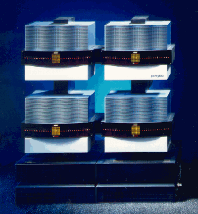
This is a picture of 4 GigaCubes (GC-2, i.e. 256 Transputers)
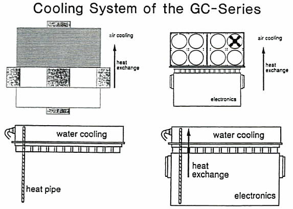
Machines larger than the GC-3 (>= 1024 processors) would have required water cooling which is facilitated by the use of “heat pipes”. Here’s a sketch I’ve found showing where the cooling was located in the GigaCube housing.
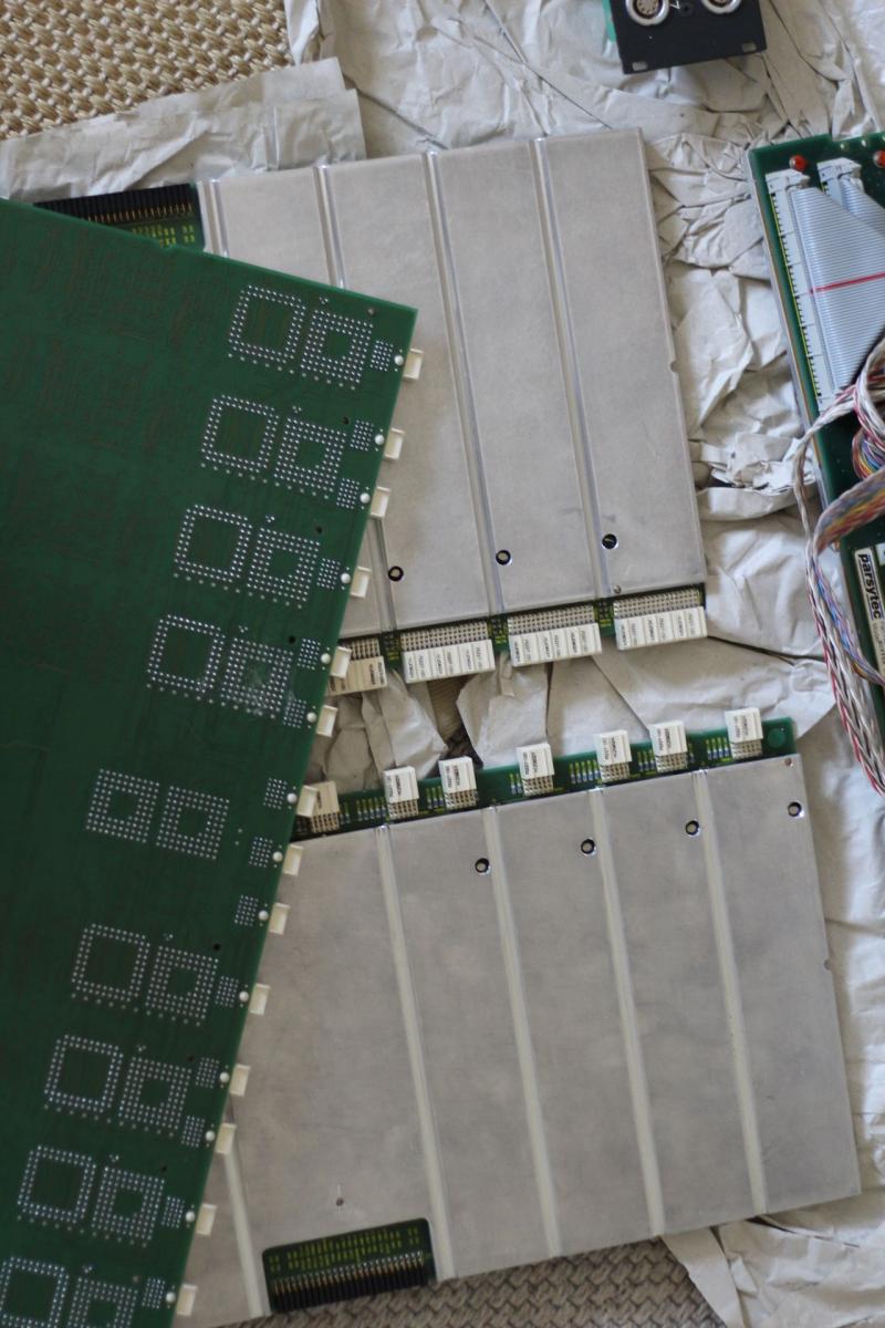
How did Parsytec connect those heat-pipes with the board? By a lucky incident a nice guy provided me with new, detailed photos describing how cooling was managed.
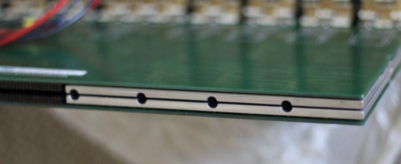
Contrary to a “normal” GigaCluster CPU board (or cluster, as described further down), CPU boards in GC-3 were covered by a massive aluminum heat-spreader, featuring “half-pipes” milled into the aluminum as shown in this picture:
When put back-to-back into the Backplane, those half-pipes created a full pipe into which the heat-pipe was “sunk”. Very clever, indeed.
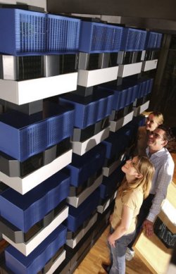
Fun-findings: If a GC-4 whould have ever been built, it would have looked like this rendering (bear in mind: 4096 Transputers!)
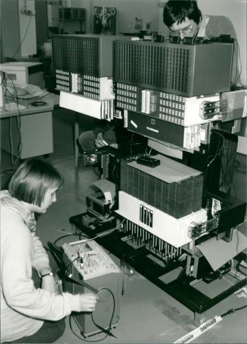
And here’s a nice press-photograph showing Angela Merkel building a GC… naah, just kidding:
Node
A GigaCube consists of four clusters of 16 processors and has self-contained redundancy, control processor, power supply and cooling.
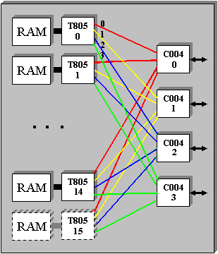
A cluster is the basic architectural unit and consists of 16 Inmos IMS T805 transputers running at 30MHz, the EDC-protected memories (up to 4Mbytes per T805), a further redundant T805, the local link connections and 4 Inmos C004 routing chips. Each link of the T805 is connected to a different C004, thus making it hardware fault tolerant. Redundancy in a cluster ensures overall probability of failure is less than that of a single typical chip.
This is a diagramm of how a cluster was connected internally:
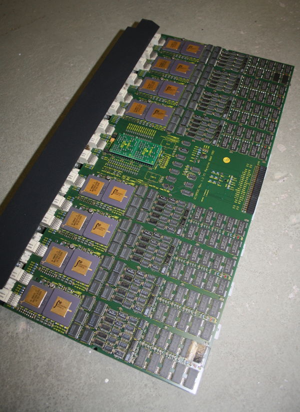
And this is a photogaph of a cluster as it was used in the Parsytec x’plorer. Besides the missing C004s it is identical to the those used in the CG:
I/O
Inside a GigaCube each processor cluster has eight dedicated links with a bidirectional bandwidth of 20 Mbytes/s. Each of the two sets of 16 links with an additional control link forms a basic I/O channel. These are logically driven by the control processor and therefore allow it to control the attached devices if required. For the largest systems shared I/O devices amongst the GigaCubes is achieved with a special module (IONM) which may be cascaded.
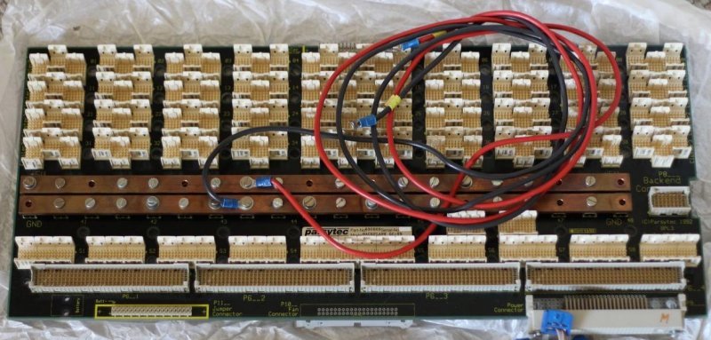
Up to 4 clusters were plugged into a Backplane which looks like this:
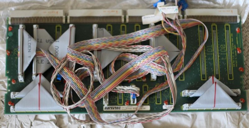
Next to the four cluster-boards, a buffer-board was seated handling the communication “outside of the cube”:
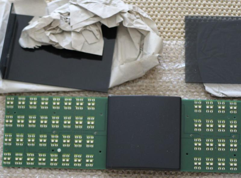
As you most certainly know, Blinkenlights is an absolute must-have (and the 6th commandment in Axels laws ;)), so each Cube had its own LED panel – 128 LEDs, 2 for each Transputer in the Cluster – hidden behind a sleek acrylic glass:
Topology
The communications structure of the machine is software configurable. Each T805 has four hard links and up to 16384 virtual links. Each hard link is connected to a C004 32×32 way cross-bar switch. The C004 can determine the destination of a message and switch automatically with extremely low latency.
Operating System
Ofically the CG-machines were meant to be used with PARIX. PARIX is based on UNIX with parallel extensions, supports Remote Procedure Call and the I/O library is a subset of the POSIX standard.
Being a “good Transputer system” the GCs can also run Helios. Helios is supporting the special reset-mechanism of Parsytec out of the box.
Parsytec was involved in the first phase of the GPMIMD project. However, disagreement with the other members, Meiko, Parsys, Inmos and Telmat, on the adoption of a single physical architecture, prompted them to announce their own T9000 machine, based on the design of the CG machines. Due to INMOS’ problems with the T9000, Parsytec switched to the Motorola 604 PowerPC CPUs. This led to their “hybrid” systems degrading Transputers as communication processors and having the PPCs doing the computational work.
While I cannot support that policy, here’s a separate Post about those bastard machines due to frequent requests 😉

