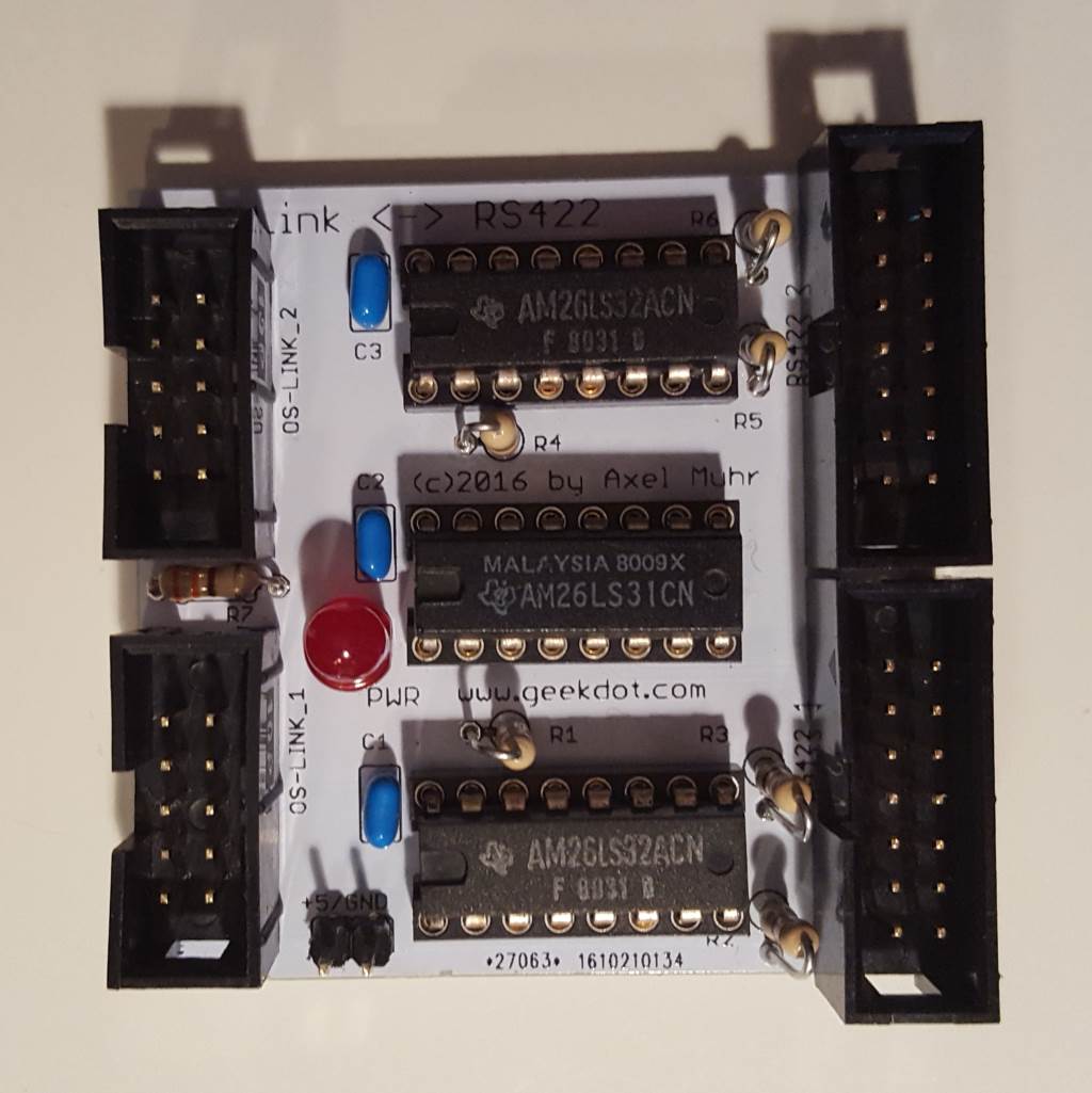
This is a Q’n’D but handy design which I was planning for a long time, but you know how things go… A differential adapter is a simple device which translates a single signal/data line in one positive and one negative line, i.e. one is carrying the inverted signal of the other. This is also known as RS422… But why do we need such thing?
Well, differential signals are/were quite common in the world of Transputing to deliver OS-link signals over longer distances (<10m/30ft) or noisy environments and good examples are systems from Parsytec, the AVM-T1, ISA interfaces like the HEMA TA2 or even some custom measure/data-logging solutions.
So to connect to such systems using a non-RS422 (i.e TTL) interface card, e.g. the INMOS B004/008 or the Gerlach-Card you’ll need such an differential adapter.
Technical data
A very simple design on a 5x5cm PCB. All done in trough-hole technology (THT) to keep this a simple DIY project.
It all based around two AM26LS32 receivers and one AM26LS31 transceiver, some resistors and an unavoidable LED 😉
Usage is very simple, too. Just connect the TTL signals to the standard 2×5 shrouded PCB header connector and RS422 signals are provided on the 2×7 header connector on the opposite side of the PCB.
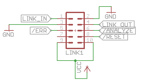
The TTL connector is the same as the one used on the Gerlach card or my T2A2 Apple II interface:
As you can see, pins 9 & 10 can provide 5V to the PCB so that no external power-supply is needed.
If you connect a system not able to provide power to the differential adapter there’s also a 2pin connector provided on the PCB itself.
The RS422-side of the adapter has this pin-layout:
Nice-to-know: You could also use this adapter to simply invert signals. For example if you need a positive ERR signal instead of the not’ed, you simply take the positive pin (i.e. even pin-number 6 in this case) of the 2×7 connector (ignoring the negative).
Mind there’s no power supply pin on that side and pins 11/12 are not connected.


