Tag Archives: design

The final Cube – Snow white coffin

This is it. Hooray! The final Cube as I always wanted it to be.
It just took me about 2 years of planning, blood, sweat & tears, huffing and puffing. Many tries to find the right parts, plenty materials evaluated always trying to keep the budget low.
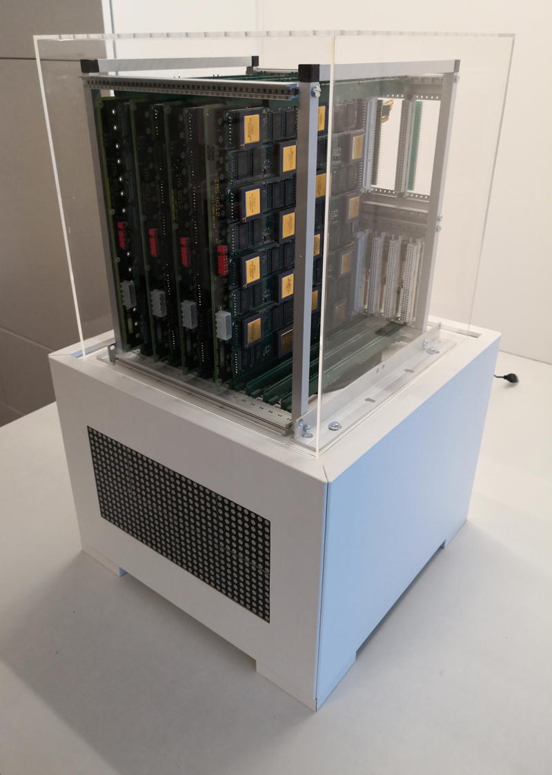
The sleeping beauty – yeah, it’s a bit snow white coffin’ish

Meet the ancestors

You might have followed the route I took for quite some time now:
It began with the ‘Tower of Power‘, basically a component carrier with a power-supply.
After some years it was replaced by the first Cube.  Well, yes, while it had a somewhat cubic’ish case, is still was just a dull standard industrial case. Not really what I imagined how my computer should look.

Form follows function

If you’ve read some posts here on GeekDot, you might already got the impression that I’m a sucker for design. Well, not that kind of a surprise, given I studied design some decades ago 🙄
I’m also heavily influenced by the works and philosophy of Dieter Rams (mainly for BRAUN) and Hartmut Esslinger (of frog design), of which you might not have heard about, but you know their designs for sure…
So I fell in love with the Parsytec x’plorer and other iconic computer designs like these ‘cubistic’ examples:

Yes, I am a strong believer that a computer, while basically being a rather boring calculation tool, should look good, timeless and might give you an idea of its innards are actually doing something.
We could probably go on forever, defining how a well designed computer should look like. But like the Romans used to say: “non potest argui per gustum” (You can’t argue about taste)…
Let’s say, I’m probably not totally off, given that most designs I like are also on display at the Museum Of Modern Art 😉

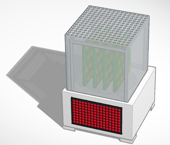
So mentioning the Final Cubes design, it’s  case we’re talking about: If you’re really picky, then yes, the Final Cube is actually two cubes:

The carrier-cage on the top which I tried to keep simplistic and invisible to give the PCBs as much stage as possible. The user should be able to see the many, shining CPUs. So 10x10mm aluminum square tubes are connected by 3D-printed frame-corners to provide maximum view onto the technology.
For protection but also as a design statement and tribute to Rams’/Gugelots famous ‘snow white’s coffin‘ everything is surrounded by a 30x30x30cm translucent acrylic cube.

The white base actually isn’t cubical at all being much wider than tall. Nevertheless, its design should be even more simplistic and cautious to serve three purposes:

  • Give the computing-parts above it a proper podium
  • House the LED array which provides the fitting aura
  • …and finally house all the tech the user should not care about

With quite a big fan between the base and the top both work like a chimney (following the convection) sucking the air from the bottom and blowing it through 169 holes in the top plate of the cube.
Here’s an idea out how it looks “working”:

When one thing comes to another

The parts of which the Final Cube is build from aren’t all created this year. Actually only the case and the cage-frame are from 2019 – all other parts were designed by me some years before.

The core of everything are TRAMs – these are Transputer computing modules defined by Inmos back in 1990. The specific TRAMs used are my own AM-B404, each containing a 25MHz T800 and 2MB of  fast SRAM.
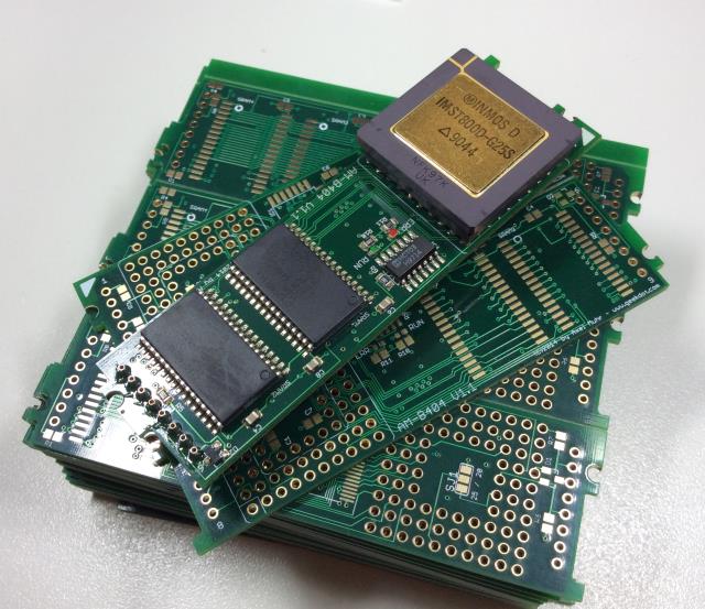
Finest home-made TRAMs

16 of these TRAMs are placed onto an Inmos B012 (or compatible) carrier board. And up to 10 of these carriers can be put into the Cubes carrier-frame creating the cluster.

Under the hood

Below the carrier-frame, in the base, you can spot a 32×16 LED panel. This one is actually from 2012 when I designed the T2i2c, an i2c-bus to Transputer TRAM.
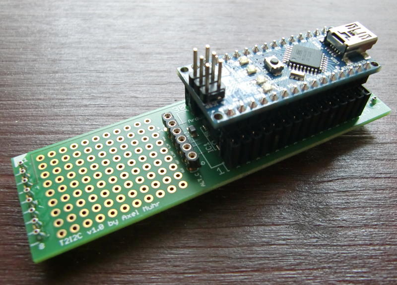
Yes, that’s an Arduino Micro on top of a TRAM

So it was a natural move to make the T2i2c into a system-controller. It does not only controls the LEDs displaying the current load of all Transputers, but also using a photo-diode to set the display brightness as well as measuring the internal temperature and overall power consumption.

Here’s an overview of the base internals:
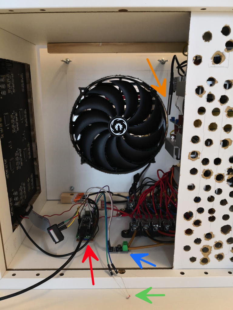
I know, the venting holes are not pretty – but they do their job and prevent you from accidentally touching the power-supply.

The red arrow points to the T2i2c being connected to the LED panel to the left as well as to a hall-sensor (blue arrow) measuring the power consumption, a temperature sensor (orange) and a photo-diode (green).
You cannot overlook the 22cm fan in the back sucking air from the bottom along the power-supply and pushing it up to the Transputers above to keep them cool.

And their power consumption is not to be trivialized. In average a single Transputer TRAM requires is about 1 ampere… so the math is easy. This means the quest for a powerful power-supply was on.
After some months I found what used to be the power-supply meant for a 3Com Corebuilder 7000: The mighty 3C37010A. A whopping 90A@5V should be OK for starters… here’s the fitting procedure:
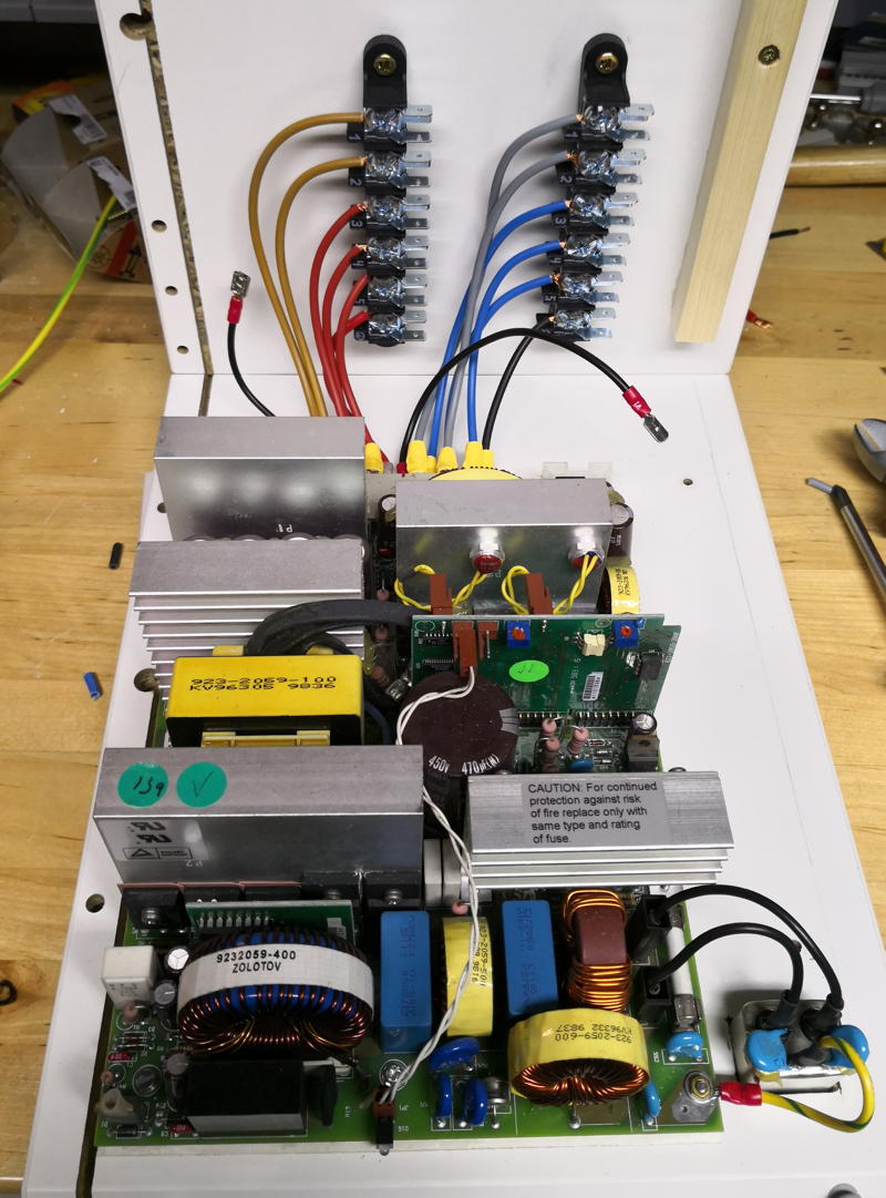
Mooooore powerrrrrrr, Igor! You touch, you die!

The back of the medal…

The backside did not change compared to the previous Cube back  – well besides the supply-cabling which now goes down into the base instead to the side of the cage.
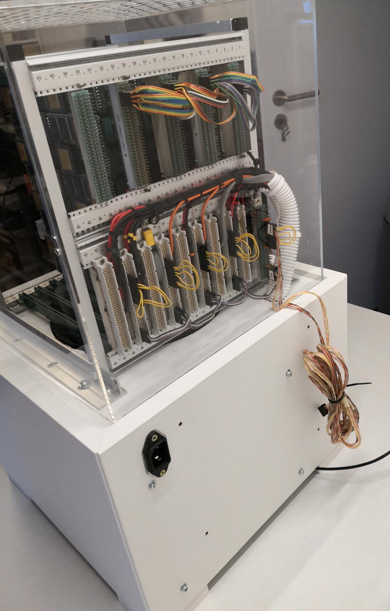

In consequence you’ll spot the power-connector there. No switch though  – still thinking about that… as well as a nicer cable-management for the link-cable which is normally connected to the host.

Next up would be a host matching the look. Mhhhh….

Sometime it just works…

Those are rare moments but sometime it happens:
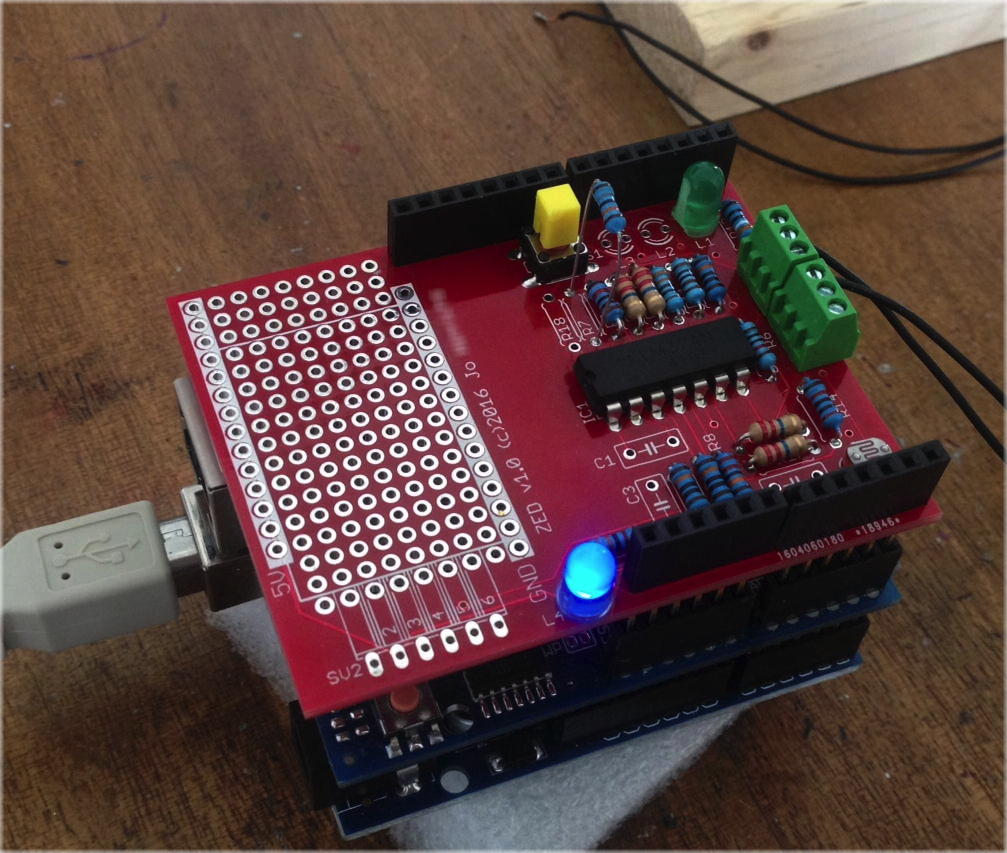
My brother-in-law gave me a very simple schematic drawing (a ppt file 🙄 ) asking if i could “turn that into reality”. It should be a Arduino shield to measure vibrations created by passing trains (in German that’s a “Zug Erschütterungs Detektor”).

Well, out went trusty Eagle CAD and some interpretation fun began. Some components were described as “resistor 1-10k” others had unknown dimensions like “pushbutton bought at eBay”.
After sending some photographs back and forth I was pretty clear that everything makes sense… and after some optimizing  the shield had plenty of space left. So in went a nice breadboard section with the option of placing a RTC there as well.

Then the DirtyPCB drill started again – and after 2.5 weeks the PCBs arrived and bro’-in-law happily started to assemble the “ZED 1.0”.
What should I say? It just worked. Immediately…  wow. That should happen more often, or like Hannibal says “I love it when a plan comes together”  😉

ZED1_0

GigaCluster

The GC system (GigaCluster) was Parsytecs entry into the Supercomputing world aiming the TOP500 list.
Actually there were two models available. The pure Transputer model was called “GCel” (GigaCluster entry level) while its successor using Motorolas PPC601 CPUs was simply called “GC”. The different sources in the Web are mixing those two model-names at random – I’m sticking to GC throughout this article, even it’s the Transputer model.

Architecture

A GC machine is built up from a number of GigaCubes. Each GigaCube represents a self-contained unit/case with its own power supply, I/O channels and interconnection to other GigaCubes. Each GigaCube contains 64 T805 processors packaged at high-density.
A GigaCube was available as a stand-alone machine, called the GC-1/64 (Peak performance = 12.8 GIPS (32-bit), 1.6 GFLOPS (64-bit))
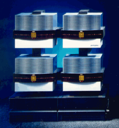
This is a picture of 4 GigaCubes (GC-2, i.e. 256 Transputers)

GigaCubeCases

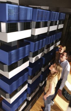
 This picture shows the biggest ever built GC. It’s the GC-3 (1024 CPUs) delivered to the university of Paderborn (Germany) which is now on display stored away somewhere in the Heinrich-Nixdorf Computer Museum in the same city (Thanks to Abraham V. giving me the update that they removed it from public display. Shame on them! – been there myself in 2018 and yes, it’s still not on display):

GC_paderborn

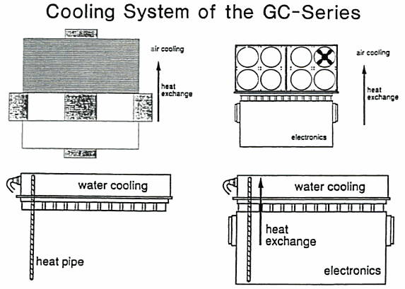
Machines larger than the GC-3 (>= 1024 processors) would have required water cooling which is facilitated by the use of “heat pipes”. Here’s a sketch I’ve found showing where the cooling was located in the GigaCube housing.

GC-Cooling

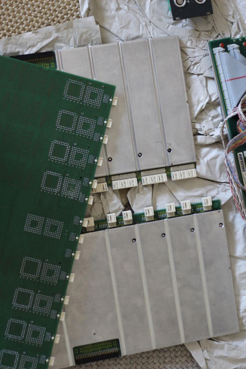
How did Parsytec connect those heat-pipes with the board? By a lucky incident a nice guy provided me with new, detailed photos describing how cooling was managed.

Contrary to a “normal” GigaCluster CPU board (or cluster, as described further down), CPU boards in GC-3 were covered by a massive aluminum heat-spreader, featuring “half-pipes” milled into the aluminum as shown in this picture:

GC_CPUboards

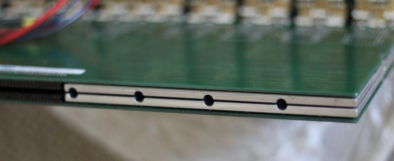
When put back-to-back into the Backplane, those half-pipes created a full pipe into which the heat-pipe was “sunk”. Very clever, indeed.

GC_CPUboardsPipes

Fun-findings: If a GC-4 whould have ever been built, it would have looked like this rendering (bear in mind: 4096 Transputers!)

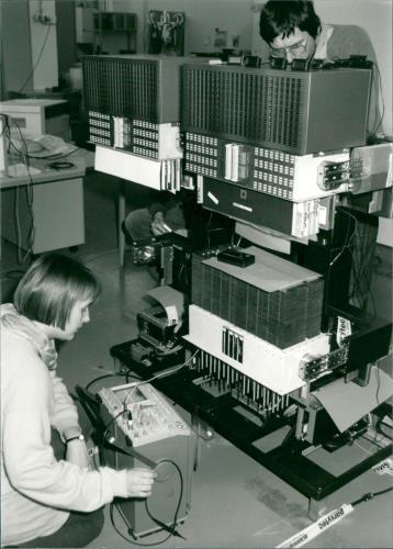
And here’s a nice press-photograph showing Angela Merkel building a GC… naah, just kidding:

Node

A GigaCube consists of four clusters of 16 processors and has self-contained redundancy, control processor, power supply and cooling.
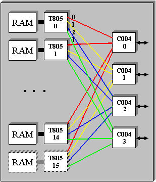
A cluster is the basic architectural unit and consists of 16 Inmos IMS T805 transputers running at 30MHz, the EDC-protected memories (up to 4Mbytes per T805), a further redundant T805, the local link connections and 4 Inmos C004 routing chips. Each link of the T805 is connected to a different C004, thus making it hardware fault tolerant. Redundancy in a cluster ensures overall probability of failure is less than that of a single typical chip.
This is a diagramm of how a cluster was connected internally:

cluster

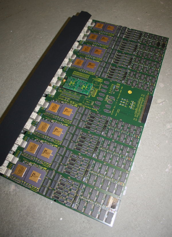
And this is a photogaph of a cluster as it was used in the Parsytec x’plorer. Besides the missing C004s it is identical to the those used in the CG:

FullBoard

I/O

Inside a GigaCube each processor cluster has eight dedicated links with a bidirectional bandwidth of 20 Mbytes/s. Each of the two sets of 16 links with an additional control link forms a basic I/O channel. These are logically driven by the control processor and therefore allow it to control the attached devices if required. For the largest systems shared I/O devices amongst the GigaCubes is achieved with a special module (IONM) which may be cascaded.

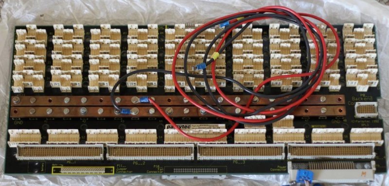
Up to 4 clusters were plugged into a Backplane which looks like this:

GC_Backplane_1

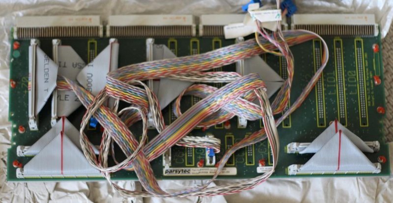
Next to the four cluster-boards, a buffer-board was seated handling the communication “outside of the cube”:

GC_Bufferboard_1

As you most certainly know, Blinkenlights is an absolute must-have (and the 6th commandment in Axels laws ;)), so each Cube had its own LED panel – 128 LEDs, 2 for each Transputer in the Cluster – hidden behind a sleek acrylic glass:

GC_LEDpanel

Topology

The communications structure of the machine is software configurable. Each T805 has four hard links and up to 16384 virtual links. Each hard link is connected to a C004 32×32 way cross-bar switch. The C004 can determine the destination of a message and switch automatically with extremely low latency.

Operating System

Ofically the CG-machines were meant to be used with PARIX. PARIX is based on UNIX with parallel extensions, supports Remote Procedure Call and the I/O library is a subset of the POSIX standard.
Being a “good Transputer system” the GCs can also run Helios. Helios is supporting the special reset-mechanism of Parsytec out of the box.

Parsytec was involved in the first phase of the GPMIMD project. However, disagreement with the other members, Meiko, Parsys, Inmos and Telmat, on the adoption of a single physical architecture, prompted them to announce their own T9000 machine, based on the design of the CG machines. Due to INMOS’ problems with the T9000, Parsytec switched to the Motorola 604 PowerPC CPUs. This led to their “hybrid” systems degrading Transputers as communication processors and having the PPCs doing the computational work.
While I cannot support that policy, here’s a separate Post about those bastard machines due to frequent requests 😉

x’plorer

It’s yet unclear how to write its name correctly. Some sources use XPlorer, others xPlorer and many other permutations. As my model has this logo at the front of its case xpl_logo

I’m going to use x’plorer. Having this burning issue off my chest, let’s go into details 😉

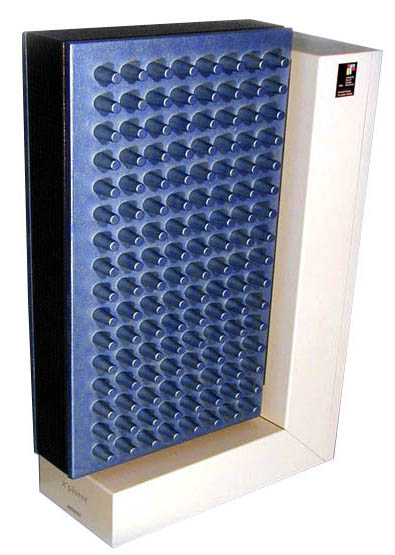
The x’plorer is more or less a single “slice” -Parsytec called them cluster– of a GigaCube, which used 4 of those clusters in its smallest 64-Transputer version (GC-1). Thus, the  x’plorer features 16 Transputers, each having access to 4MB RAM in a gorgeousdesktop case. If you want, you could call it a “GC-0.25”. xplorer_freigestellt

Sorry, but I have to rave a bit over its case design. I first saw it at CeBit fair 1995, when is was on display at the “IF forum design” (I explained that in the Parsytec intro already). I was literally pulled through the room and stood in front of it for minutes.
It looked like a typical FROG design work (Famous for the NeXT cube, Apple //c, some 68k Macs, SPARC Stations and much more) and I told this everybody who asked… but I just figured out I was wrong and it was actually designed by a relatively small studio called Via 4 Design.

The grey L-shaped base/back is made of sheet metal and contains the power supply in the base, a tiny bit of logic (described further down) and 2 big fans in the back.

The big blue main body is made of cast metal – no puny plastic crap. Yes, it’s heavy.
At first sight everybody thinks “hey, that’s a clever design, using the case as a heat sink!”. That’s obvious as those fingers/burlings sticking out to the left and right really do look like they are just that. And yes, as far as I was told, initially they planned to use them for cooling to circumvent noisy fans… but for some reason this didn’t work out and so they’re just a -admittedly very cool- design element.

Dissection

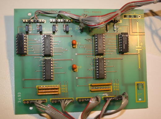
Let’s open that beauty. After loosening two screws at the back you can remove the whole back-panel holding the 2 big fans. The first you’ll see will be a rather simple, 2-layer circuit board  containing the RS422 interface logic, i.e. 2 Am2631 and 2 Am2632.
This is the board removed from the case. Front:

RS422_1

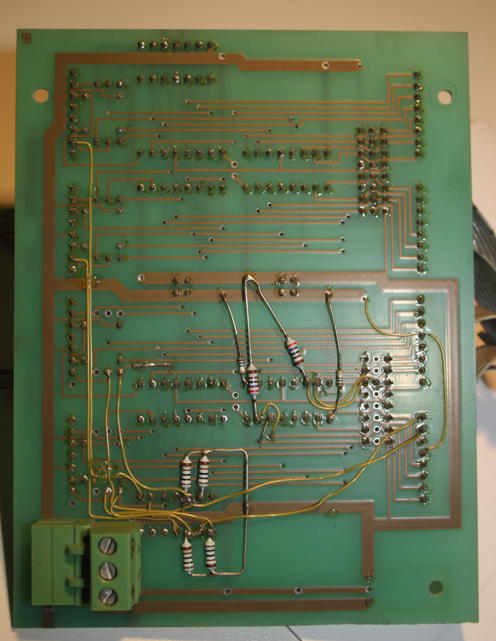
….and the back. A bit patched, some resistors added.

RS422_3

Those extra cables and resistors were retrofitted to allow the user to “partition” the x’plorer into either 1×16 or 2×8 Transputers. Therefore my x’plorer has a simple switch on its back to either select the full or half system. As there are 4 connectors in the back (2x TTL, 2x RS422) two users can use the system at the same time.

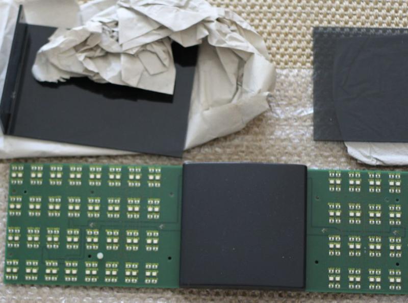
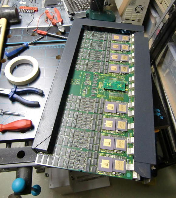
After removing the L-Shaped base from the main part, you can slide-out the blue side-panels leaving you with the dark grey frame holding the main circuit board… looking like this:

xPlorer_Workbench

You might wonder about the ‘workshop environment’ – well, actually you need quite some tools to open the x’plorer. Like with some Italian cars ;-), you need a different screwdriver for each screw. Here’s what I remember: Allen key size 2, 2.5 and 3. Also handy are a Torx size 3 and a Phillips size 2 as well a a rubber hammer to carefully removing the dark-grey frame (consists of 3 parts).
All in all, given the wild mixture of techniques and material used, I have the strange feeling that the x’plorer was created in a somewhat shirt-sleeve approach.

After some wiggling, careful knocking and a bit of cursing, you will have the main circuit-board laying in front of you – actually there are two boards, back-to-back, connected by a tiny backplane still hidden in the metal frame in the picture below.
Definitely this is the high-tech part of the whole x’plorer using state-of-the-art technology of its time (1992):

FullBoard

A closer look

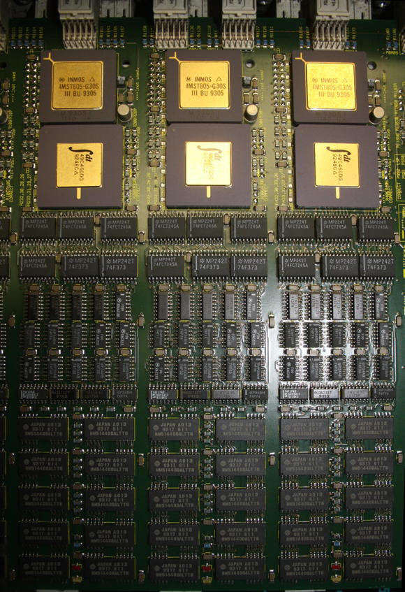
The boards layout is nice and clean. You can understand its design by simply looking at it – so let’s do so. Here’s a top-view of 3 ‘Blocks’ or ‘Columns’ as an example… all 16 look the same:

Topview_3_blocks

At the Top there’s the T805-30MHz Transputer. Right below is an IDT49C460 which is a 32-bit Error Detection and Correction chip which generates check bits on a 32-bit data field. Then there a lots of buffers and drivers which connect to the 4MB of RAM below them (80ns, so 4 cycle speed). Nice little feature: 2 SMD LEDs for error and running.

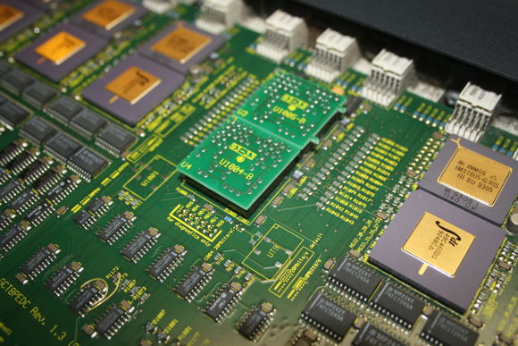
On each side, between 4 of those ‘blocks’ are two of those little circuit boards seated in 2 sockets (labelled ‘U1004’ and ‘U1005’). These are hard-wire replacements for the normally installed C004 link switches. Normally means if this cluster would have been installed in a GigaCube, there would be 4 C004s on each cluster allowing free and dynamic configuration of the Transputer network topology. So in an x’plorer you have to live with a fixed 4×4 network, which is not bad, because configuring 4 C004s can be painful 😉

C004_dummies1

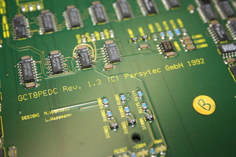
At the same spot, there’s a nice marking of the ‘fathers’ of this board, namely Mr. M.Vyskcocil and L. Wassmann.
Also, the official product name of this board is “GCT8PEDC” and it’s Revision 1.3.

Model_GCT8PEDC

The “other x’plorer”

Well, yes, there was another x’plorer in existence. As with the GC-system, Parsytec later offered the “PowerXplorer”- you may guessed it already: It used the cluster from the PPC601 powered GC systems. I wrote a dedicated post over here about those hybrids, bastards, you-name-it 😉

Let’s roll

Now that we know what’s inside that beautiful case, let’s see if it’s still working. As mentioned before, Parsytec had a special way of resetting the Transputer(s). Instead of resetting all the Transputers in the network the same time (like INMOS did), Parsytec systems had been designed that each Transputer can reset its 4 direct neighbours. So you need to load a special software into a Transputer to do so.
That said, after powering-on the system, all Transputers will be reset automatically. This is the only chance to run standard Trasputer tools like ‘ispy’… once.

So I connected my trusty old Gerlach card to my selfbuilt RS422 interface and brought a cable from there into the x’plorer.
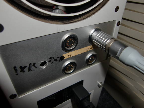
At its back, the x’plorer features four 8-pin sockets made by LEMO (Sockets are EGG.2B.308, so the plug might be FGG.2B.308 I guess) lloking like this:

xpl_connectors


If you’re lucky enough to own one of those expensive plugs/cables, this is the wireing:

      1        1 Reset out+    2 Reset out-
   2     8     3 Link out+     4 link out-
  3       7    5 Link in-      6 Link in+
   4     6     7 Reset in-     8 Reset in+
      5

I you don’t have a LEMO plug, use the 2×5 sockets inside the x’plorer case right behind the LEMO sockets.  Their pin-out should be:

10  RO+  RO-  9
 8  LO+  LO-  7
 6  NC   NC   5
 4  LI-  LI+  3
 2  RI-  RI+  1

Now let’s call ispy and see what happens…

Using 150 ispy 3.23 | mtest 3.22
# Part rate Link# [  Link0  Link1  Link2  Link3 ] RAM,cycle
0 T800d-24 265k 0 [   HOST    1:0    ...    ... ] 4K,1 1024K,3;
1 T805d-30 1.3M 0 [    0:1    2:1    3:2    4:3 ] 4K,1 4092K,4.
2 T805d-30 1.8M 1 [    5:0    1:1    6:2    7:3 ] 4K,1 4092K,4.
3 T805d-30 1.8M 2 [    7:0    ...    1:2    8:3 ] 4K,1 4092K,4.
4 T805d-30 1.8M 3 [    6:0    ...    ...    1:3 ] 4K,1 4092K,4.
5 T805d-30 1.8M 0 [    2:0    9:1   10:2   11:3 ] 4K,1 4092K,4.
6 T805d-30 1.8M 2 [    4:0   11:1    2:2    ... ] 4K,1 4092K,4.
7 T805d-30 1.8M 3 [    3:0   10:1   12:2    2:3 ] 4K,1 4092K,4.
8 T805d-30 1.8M 3 [    ...   12:1    ...    3:3 ] 4K,1 4092K,4.
9 T805d-30 1.8M 1 [    ...    5:1   13:2   14:3 ] 4K,1 4092K,4.
10 T805d-30 1.8M 2 [   14:0    7:1    5:2   15:3 ] 4K,1 4092K,4.
11 T805d-30 1.8M 3 [   13:0    6:1    ...    5:3 ] 4K,1 4092K,4.
12 T805d-30 1.8M 2 [   15:0    8:1    7:2    ... ] 4K,1 4092K,4.
13 T805d-30 1.8M 2 [   11:0    ...    9:2    ... ] 4K,1 4092K,4.
14 T805d-30 1.8M 3 [   10:0    ...   16:2    9:3 ] 4K,1 4092K,4.
15 T805d-30 1.8M 3 [   12:0   16:1    ...   10:3 ] 4K,1 4092K,4.
16 T805d-30 1.8M 2 [    ...   15:1   14:2    ... ] 4K,1 4092K,4.

Tadaa! There they are: 16 30MHz Transputers running at full steam ahead! Some intense brain-boggling hours later, I was able to draw a “mesh-map”:

Host
|
4---1---3---8
|   |   |   |
6---2---7--12
|   |   |   |
11--5--10--15
|   |   |   |
13--9--14--16

After this ispy run you can’t reset the network again if you don’t use proper Parsytec tools… or Helios.

So quickly running the ispy output through my little Perl script (available in the Helios chapter on this page), some small adjustments and here it is, the Helios network map:

Network /Net {
Processor 00 { ~IO, ~01, , ; system; }
Processor IO { ~00; IO; }
{
Reset { driver; ; pa_ra.d }
processor 01 { ~00, ~02, ~03, ~04; }
processor 02 { ~05, ~01, ~06, ~07; }
processor 03 { ~07,    , ~01, ~08; }
processor 04 { ~06,    ,    , ~01; }
processor 05 { ~02, ~09, ~10, ~11; }
processor 06 { ~04, ~11, ~02,    ; }
processor 07 { ~03, ~10, ~12, ~02; }
processor 08 {    , ~12,    , ~03; }
processor 09 {    , ~05, ~13, ~14; }
processor 10 { ~14, ~07, ~05, ~15; }
processor 11 { ~13, ~06,    , ~05; }
processor 12 { ~15, ~08, ~07,    ; }
processor 13 { ~11,    , ~09,    ; }
processor 14 { ~10,    , ~16, ~09; }
processor 15 { ~12, ~16,    , ~10; }
processor 16 {    , ~15, ~14,    ; }
}
}

Obviously you have to ‘compile’ a .map file out of that and adjust your initrc file – all this is described in the above mentioned Helios chapter.
When you have done everything correctly, Helios will happily boot your x’plorer and you can enjoy the mighty power of 16 (well, 17) Transputers!