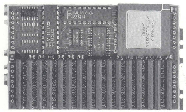
Tag Archives: TRAM

T2shield – Arduino to Transputers

[The T2shield is currently a work-in-progress project – the first alpha hardware is operating but lots of coding lies ahead!!]

The idea for the T2shield was born when I thought about getting recent peripherals like SD-cards, Ethernet, displays etc. into a Transputer network.
Sure, there are the old, original TRAMs like the STM228 SCSI controller, the B431 Ethernet TRAM or quite some choice of graphics controllers. But they’re all rare like chicken teeth these days which means unaffordable when they rarely pop up on ePay.
Rebuilding them is also a no-no given the obsolete parts they’ve used… and to be honest: A noisy, vintage SCSI-1 drive isn’t what I thought of.
So after some time I came to the conclusion it will be the easiest and cheapest way to re-use what you can buy for a few bucks from China these days: Arduino shields.
As a lucky incident such a shield perfectly fits onto a size-2 TRAM – Yay!

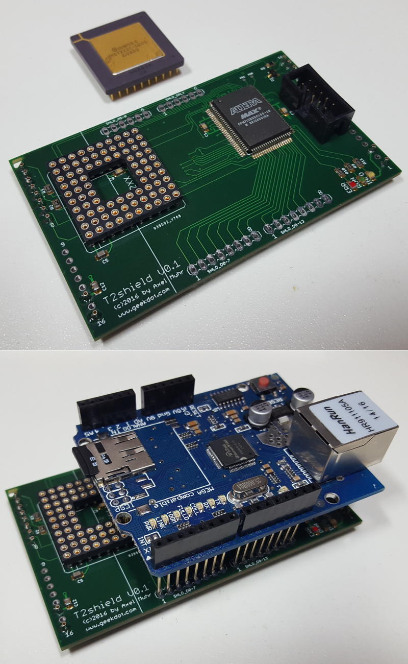
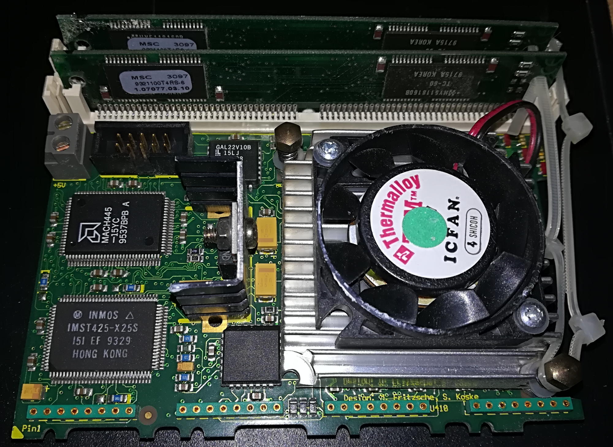
Without much further ado, here is the T2shield (v0.1) with a shield loosely put on top to get an idea…

t2shield

Arduino shields mainly use the SPI bus for data transfer. With its 10+Mbps SPI is much faster than e.g. I²C (which I used for my T2I2C TRAM) and can cope with fast(er) peripherals.
But this also ruled out a slow IMSC011/12 link-adapter design like the one used on the T2I2C. Also there’s no of-the-shelve SPI master controller to simply glue a bus to it.
So the design turned out much more advanced this time:

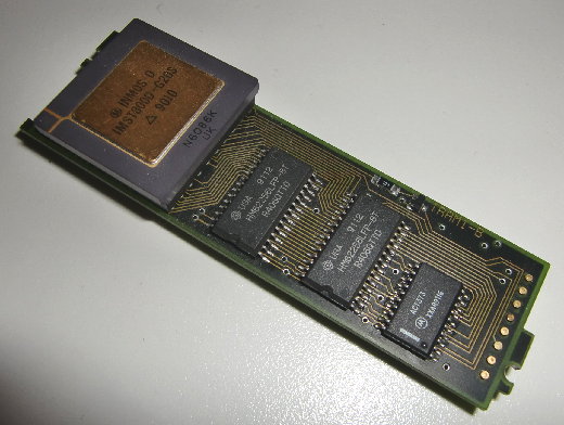
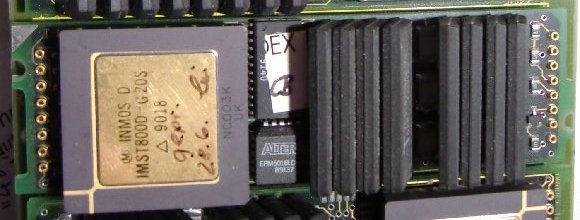
  • A 16bit Transputer (with 64KB SRAM) handles the high OS-link speeds as well as the ‘glue’ like File/Ethernet handling.
  • A comparably big CPLD (100pins, 128 marcocells) implements the SPI master controller as well as handles the T2xx memory- and interrupt-handling.
  • All Arduino digital-pins and nearly all analog-pins are connected to the CPLD to adjust to any available shield.

Also this new TRAM design is a “first” for me in many aspects:

  • 1st usage of a 16-bit T2xx Transputer (vs. 32bit)
  • 1st serious utilization of a CPLD (besides the baby-steps taken with the T2A2)
  • 1st Size-2 TRAM

Initial status

Transputer

[wppb progress =100 option=green] 100% done

A T222 Transputer is -after fixing some stupid errors- happily running and has control over his external RAM.
Here’s the first sign of life by RSPY (a brilliant ispy‘ish tool of Michael I really need to write a post about soon):

# Part rt Link0 Link1 Link2 Link3 RAM@cycle
0 T2   20 HOST  ...   ...   ...   4K@1,56K@2|

That means: A T2xx @ 20mbps linkspeed is connected to the host (PC) and has 4K internal and 56K external RAM… wait a second! just 56K? Yes, that’s because the internal 4K overlaps and RSPY leaves the up-most 4K untouched as most peripherals are mapped there and poking there could create unwanted effects…

CPLD

[wppb progress =10 option=yellow] 10% done

All basic Transputer controls are in place, LEDs are controlled by the CPLD

TODO: Implement the SPI master in VHDL. That’s THE biggest challenge for me being a total VHDL noob. Again, I wouldn’t got this far already without the tremendous help from Michael Brüstle, my VHDL Jedi-Master.

Drivers

[wppb progress =100 option=red] 0% done

Write the (Helios) driver to handle file and/or network access. This should be (optimistically) be compatible to existing file- or Ethernet ‘servers’. This will probably be the most time consuming task.

Progress?

This is (also) the first time I’m posting about a project which is not finished. So I will keep you posted about the progress with new posts in this “T2shield” chapter of this wonderful little page.
If you do own

  • a Transputer network
  • a free size-2 TRAM slot
  • a T2xx Transputer
  • some VHDL/Occam/Helios driver skills & knowledge

shoot me a mail and I might provide you a T2shield to join the development.

That said, here’s a first little sign of life:
The Transputer writes numbers to a mem-mapped address (0xFC00) while the CPLD reads the lowest 2 bits and displays them by 2 of the 3 LEDs on the T2shield

Inmos B008

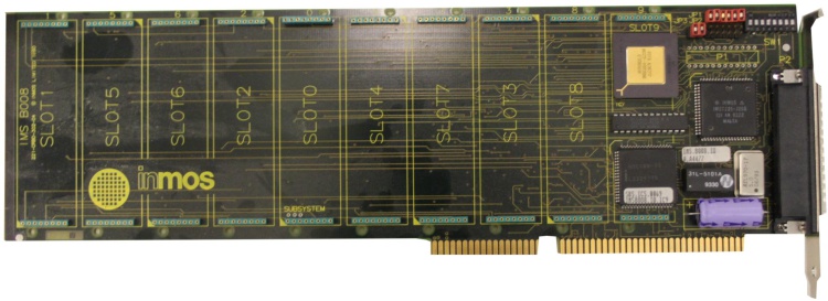
Introduced at the sunset of the Transputer era, the INMOS B008 was the successor of the B004 of which it dramatically differed:

  • 16-bit ISA connector (for Interrupts/DMA, it’s still an 8 bit data path)
  • 10 TRAM slots
  • C004 and T2xx on board

The usual source provides the full manual/documentation… down to the GAL equations.
All these enhancements enabled the B008 to create simple, yet powerful Transputer networks on a single expansion card and still makes it the perfect platform for todays Transputer retro experiments/fiddlings.

Here’s a late “Rev.F” version of the IMSB008:

IMSB008E

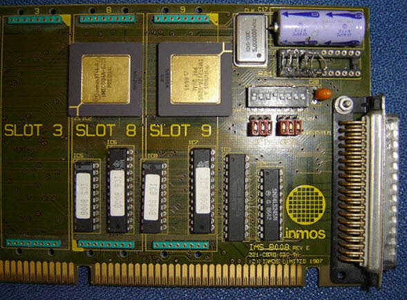
The previous revision E had a ceramic version of the T2xx and used GALs instead of the CPLD you can stop in aboves picture.

B008_revE

Clones

Obviously the Inmos B008 had clones as the B004 did.

Transtech TMB08

Well, I guess there’s nothing which Transtech did not clone and/or improve…
In this case they used a AMD MACH CPLD from the beginning, a PLCC version of the T225 and everything else was SMD.

TMB08

Alta SuperLink/XL Transputer PC Card

Alta Technology was a spin-off of Computer System Architects (CSA).
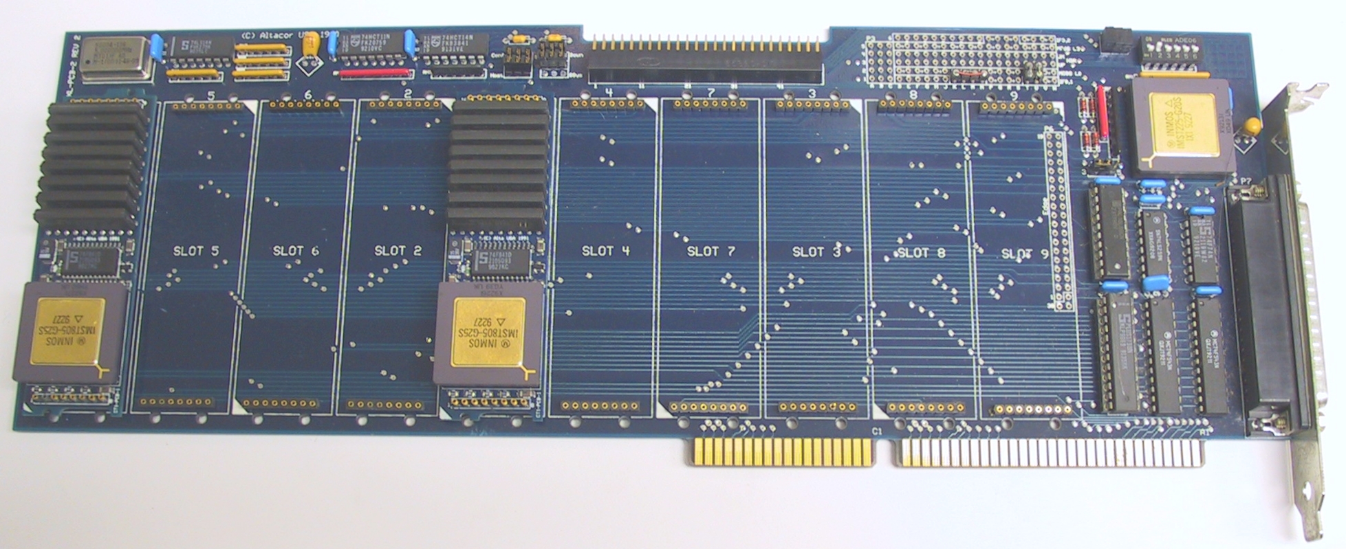
The SuperLink/XL board used TRAM modules like the Inmos B008, but featured a 20 MHz IMST225 Transputer to handle external interfacing and a beefed-up host interface design. Like the B008 it supported 10 TRAM’s

Altacor SuperLink XL

ARADEX

One of my first TRAMs was an ARADEX one, so this is a first for me, too. Actually I wasn’t aware that ARADEX also made TRAM carriers… but they seem to do quite some:

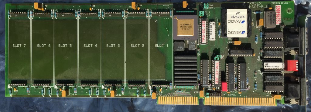
TransAT Plus

Their interpretation of the B008 theme features just 8 TRAM slots (vs. the 10 “standard”) which are strangely enough sorted in ascending order (0-7) and not like the B008 order of 1, 5, 6, 2, 0, 4, 7, 3, 8, 9. Also the TransAT provides two 9pin D-subminiature connectors in contrast to the B008s 37pin connector – most likely its layout is the so called Aalener Link-Interface. That includes the RS-422 differential drivers and receivers next to the connector (AM26LS23’s and AM26LS33’s).

Concerning other parts, besides an C012 they used some sort of CPLD – presumably to control the 16 bit bus – in the photos I have, I can clearly see the traces coming form the ISA Bus’ D[8-15].
It also uses the IRQs 10-12.

Last fun bit: They named the two GALs with their JED filenames. Very handy 😉

aradex_transat-plus

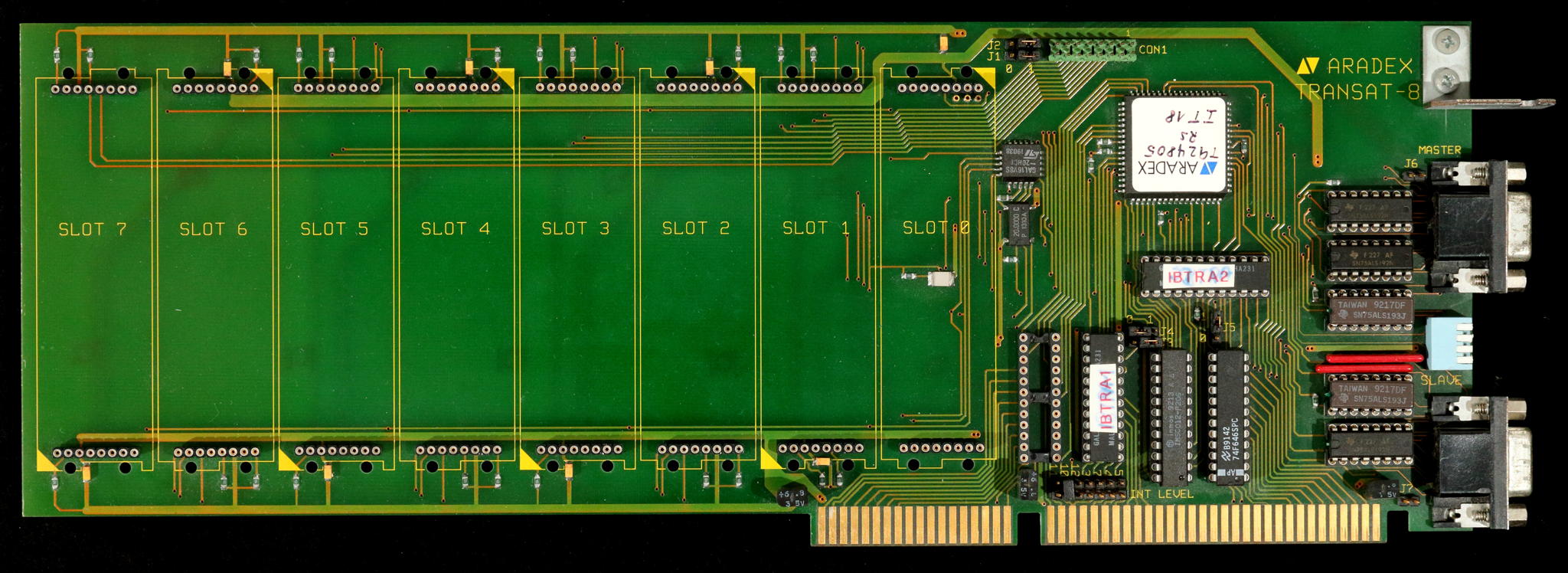
TransAT-8

The “8” in its name makes it a valid member of this collection – but it misses an C004 and also has just 8 TRAM slots… so maybe it should be considered somewhere between an IMSB004 and B008?

This time TIs 74ALS192/193 differential drivers are used, the PLCC chip is yet unknown… and in this case, a TTL chip (next to the ISA slot) is missing… all in all, it looks like a refresh of the TransAT Plus to me.

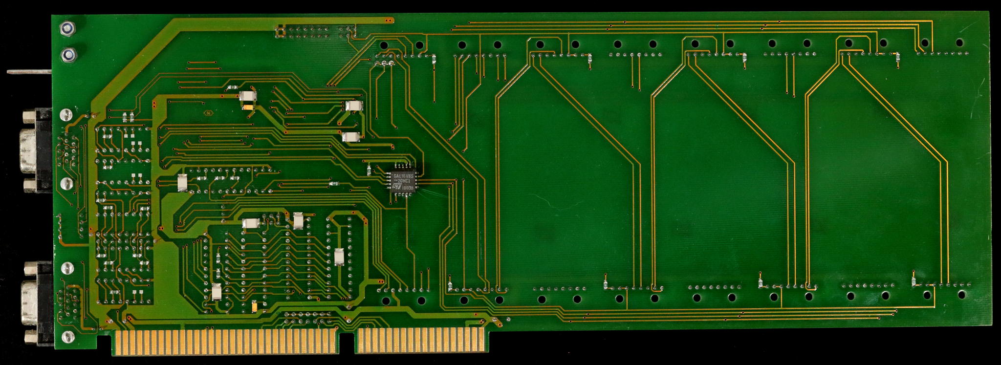
I even have a piccy of the back-side. Why the heck is somebody putting a GAL there?

Deciphering the INMOS IMSB430

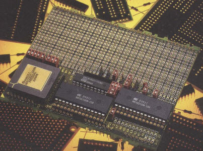
The IMSB430 is a rare, yet interesting and important TRAM. It’s been meant for hardware developers to easily build and test prototypes before producing actual PCBs.

Interesting enough, next to no documentation besides a sales brochure has survived. So it’s time for reverse engineering… again. This is also an official call for help – If you by any chance know more about this TRAM, please contact me!

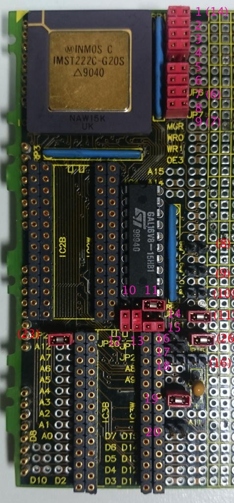
Here’s the left side of this size-4 TRAM. The other half is just the prototyping grid with lots of through holes which we can omit here.
I tried to number all jumpers on the board starting at the top – numbers in brackets are the jumper-numbers actually printed on the boards silk-screen. That numbering is a bit confusing and seems not to follow any logic.

IMSB430 Map

IC connections

Buzzing through all lines from/to the GAL leads to this table so far:

1 ProcClkOut 20 VCC
2 A13 19 Mem0 (IC2B „/CE“ + JP26)
3 A14 18 Mem1 (IC3B „/CE“ + „J20“)
4 A15 17 1Wait (IO 2-above JP8)
5 notMemCE 16 2Wait (IO above JP8)
6 WaitSEL0 (JP8) 15 3Wait (IO below JP8)
7 WaitSEL1 (JP9) 14 SelWait (MemWait+ IO below JP9)
8 Map0 (JP10) 13 BLK0 (IO below JP10)
9 Map1 (JP11) 12 BLK1 („IO1“ below JP11)
10 GND 11 (I/OE) GNDed

Each SRAM socket is actually a “double row”.
If you seat your SRAMs aligned to the right, they will be accessed word-wide (16bit, D0-A15). When aligned to the left, they are accessed byte-wide (8bit, D0-A7). That’s why the silkscreen print says “IC2B/IC2W“…

Jumpers

This is the official press photo. It seems to show the default jumper settings (using the full 64KB SRAM, word-access):

IMSB430_official

Some jumpers are already identified (“JP” precedes the official jumpers, “J” is my numbering):

Jumper description
 1  MemWait (FIT=GalPin14, else ????)
 2  DisIntRam (FIT=use internal RAM)
 3  ProcSpeedSel0 (FIT=HoldToGnd T222)
 4  MemReq (FIT=no request)
 5  EventReq (FIT=no request)
 6  MemBacc (FIT=word access)
 7 (JP6)  ProcSpeedSel2 (FIT=HoldToGnd T222)
 8  BootFromRom (FIT=BootFromLink)
 9 (JP7)  ProcSpeedSel1 (FIT=HoldToGnd T222)
JP8 Set MemWaitstate Bit0
JP9 Set MemWaitstate Bit1
JP26 Connects /OE with /CE of IC2 (upper SRAM)
J20 Connects /OE with /CE of IC3 (lower SRAM)

The external RAM access wait-states can be set with JP8/9:

JP8 + JP9 = 2 clock-cycles per MemAccess
JP9 = 3 clock-cycles
JP8 = 4 clock-cycles
none = 5 clock-cycles

To be continued…

Handling TRAMS

General caveats

TRAM pins are thinner than normal PCB-Pins e.g. those you may know from Arduino shields and thus they are, well, quite fragile. That’s a problem (by design) with all TRAMs. So be very careful when handling TRAMs, i.e. removing/plugging them from/into your TRAM carrier e.g. a IMS B008.

And you can’t repeat this enough: Ground yourself! Electrostatic discharge will kill your TRAM as well as any other electronic device.

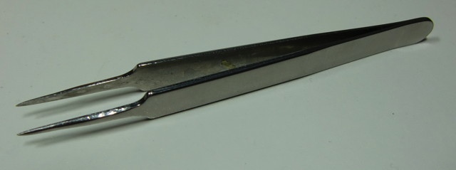
How do I do it? My main and single tool for handling TRAMs is this pair of straight tweezers:

Pliers

This works quite well for carefully removing TRAMs from its socket by putting it between TRAM and socket like this and gently lever the TRAM – not too much! Else you will bent the pins on the other side – repeat on the other side. Done.

The Transputer

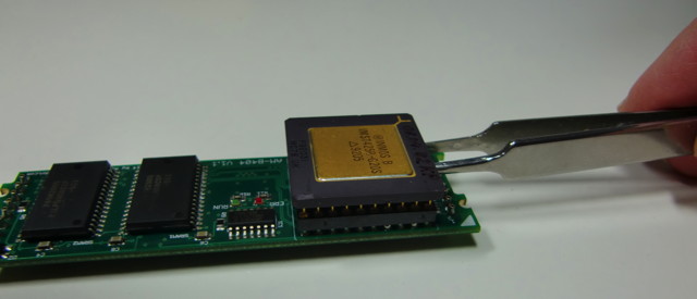
If you got you TRAM without a Transputer plugged in, you might figure that it’s quite difficult to plug in the CPU. My suggestion:

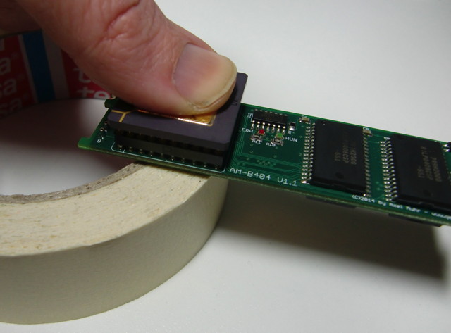
Put the back of the TRAM (the socket pins only – refrain from putting any force onto the TRAM pins) on a medium-soft item, e.g. a block of wood or like I usually do it, onto the rim of a sticky-tape roll, and press the CPU using even force into the socket with your thumb.
Double check that all CPU pins are straight and are sliding into the socket holes without force and fiddling. Also, mind the CPU orientation!
Again, never push the Transputer into its socket without support underneath the socket, your TRAM will bend and traces might break rendering it useless. At minimum the TRAM-pins will be damaged.

CPUpress

It’s worse when you’re in need of removing the CPU. Sometimes the ceramic packaging is extremely brittle and the CPU pins do sit very tight in the socket.

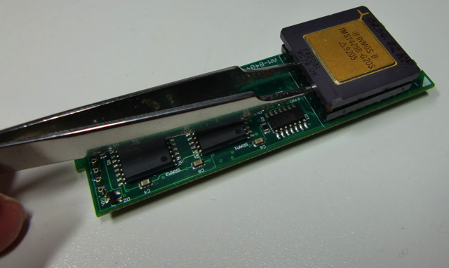
Again, use a straight tweezer, gently pushed between the socket and the CPU and carefully lever the CPU for a millimeter max.

CPUlever2

Repeat on all four sides of the CPU…

CPUlever1

The AM-B404

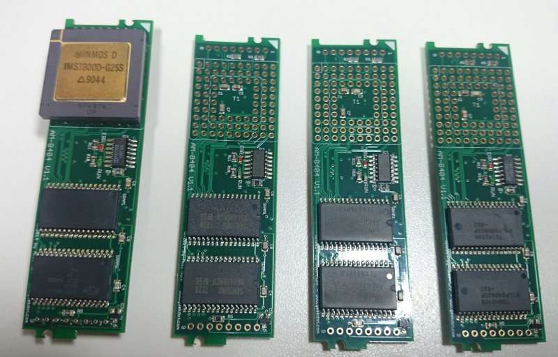
Here it is, my latest baby, the goal I was aiming for since years (4 to be exact) – not only to get more TRAMs for my systems but also to break the insane price spiral developing in the last years on ePay and other places. >300$ for a TRAM is crazy. Do not pay that amount! Even $100 is too much.

Update: Final version finished! Click here or scroll down for more.
Update 2: You can buy one, if you like…

AMB404-Front-small

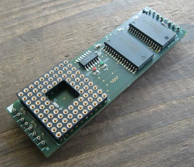
My first CPU TRAM called AM-B404 in reminiscence to the IMS-B404 which comes closest to its specs:

  • Size-1 TRAM
  • 2MB low-power SRAM
  • 2 LEDs showing the Transputers status (running and error)

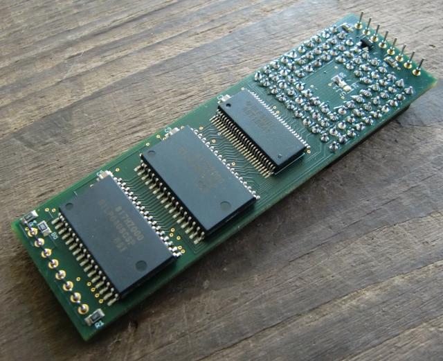
Well, the original Inmos B404 had 2MB DRAM, too (and additional 32k SRAM) but was a Size-2 TRAM and LEDs weren’t available on any Inmos TRAM… and we all know how important LEDs are! 😉 Contrary to the IMS-B404, the AM-B404 is low-profile, SRAM-only, so the whole RAM is accessed at 3-cycles vs. the IMS-B404 4-cycle DRAM.
Using a 6-layer PCB and all-modern SMD parts (well, as modern as 5V parts can get) the power consumption is a bit lower, too. I’d say about 100mA for the whole Board (no Transputer of course). Finally, there’s an easy access solder-bridge on the backside to set the CPU clock (20/25MHz).

AMB404-Back-small

This is just the 1st prototype. After thorough testing, I will optimize its layout a tiny bit and give it the proper shape of a TRAM. When that’s done, we’ll see how I can make you a realistic price offer.

UPDATE:

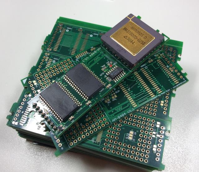
From Shenzen with love. The final PCB designes arrived and the first test went perfectly fine.

AM-B404stack

And here are the first 4 PCBs waiting to be finished with the Trough-Hole parts (i.e. Transputer Socket and TRAM Pins)… 100 solder-points in total… per TRAM. That’s quite a bit to solder :-/

First4

Video

Finally, here’s a short video showing the prototype AM-B404 in action (running Helios on my Inmos B020). The “exciting” thing is the blinking green LED which shows the CPUs activity. There’s even some brief red LED access (error) during boot-up which is triggered by Helios scanning the Transputer network.
The bright blue LED to the left is the T2i2c TRAM, so all TRAMs on the B020 are built by me now 😉

Want one?

If you hate the greedy ePay prices like I do, drop me a mail. I might have some AM-B404 left… even with T425/T800 Transputers.

Can I have the schematics?

No, not yet. Sorry. I have to break-even on this first…
Since people discovered there’s serious money in the retro-scene, some ‘smart guys’ started to clone every PCB they can get their hands on and thereby steal the initial investment which the original creators made.

I sell them a bit over the price they cost me to produce. And trust me, you won’t be able to go lower than me:
It’s a 6 layer PCB. ENIG Gold.
Sadly SRAM did not get cheaper, really. Especially the (obsolete) 5V 512kx8 I’m using were lately discovered by other projects to be very convenient and so the battle for SRAM was on. If you’re lucky you might get one for 4€… and you need 4 of them.
The 16 pins used to connect the TRAM to its carrier are very special. You have to buy them by the 1000s – 0.15€ a pop… you do the math.

T2I2C – The nitty-gritty details

Ok, so you saw the thing in action and now you want to know more – maybe even build an interface yourself because you’re one of the other ~15 guys on this planet still fooling around with Transputers 😉

Good news! This time I created circuit diagram so you can actually make you own T2I2C – and that’s not enough: I’ve already laid out a TRAM-1 size circuit board using SMD parts of the C011 and 8574 making space for piggy-backing an Arduino Uno on top of that board.

But let’s start with the other details I mentioned the chapter before. I’m totally aware that there are many, many things to improve and optimize – and then there are probably even more I’m not aware of.
Here’s the how and why I did things they way I did:

Oneway

For this first version of T2I2C I’m using an C011 in ‘mode 1’ – that means it is offering actually two 8-bit buses, one for receiving (input, I0-7)) and one for transmitting (output, Q0-7). Because it’s quick and easy I don’t use the I-bus and therefor grounded it.
This means there’s no way for the Arduino to talk to the Transputer side of things. But using an extra bus for input would mean using a second 8574 and obviously using another 4 wires on the ATMega.

The elegant solution to this is using the C011 in ‘mode-2’ – it then behaves like a C012 which means it provides a single butbidirectional 8-bit bus. So why didn’t I used mode-2 in the first-place?
Well, while mode-1 just requires 2 lines for data-control, mode-2 needs 4 lines and some more coding in the ATMega ‘firmware’ e.g. handling the 2 registers provided by a C012 – So yes, I was just lazy and wanted results quick. The next release will certainly use mode-2.

Handshaking

So what is that data-control you’ve mentioned? Using 2 converters (C011/8574) in a row there’s obviously a need for all parties to know when data has arrived and needs to be processed.
The C011 as well as the 8574 provide a pin which flags a “hey, we have something here!” signal (QValid in the C011, /INT in the 8574) . But in contrast to the 8574 the C011 also needs an “Ok, got the data, feel free to fetch the next one” – which is called “QAck”. So the ATMega controls the data-flow talking to the C011 and completely ignores the 8574 which makes it somewhat transparent.
The comms protocol of the C011 can be found in its data-sheet here. It’s all about reading, holding and releasing QValid/QAck in the right timing.

First I was using an external interrupt line on the ATMega connected to QValid because it’s so obvious. But somehow the results were flaky – sometimes the ATMega seemed do choke on some bytes which simply didn’t make it through(*). After some cursing and hair-ripping I decided to switch back to polling – again because I was lazy and wanted to get results 😉
Up to now polling QValid just works great, probably because the ATMega is pretty fast and I2C is pretty slow.
(*) Yes, of course I’ve read all the docs about interrupt-programing and its caveats (short routines, volatile vars etc…) didn’t help.

Achtung! Kommando!

So what is actually going on in the ATMega running “Se Fiiiirmwarrre”? As mentioned in the previous chapter, I decided not to send a complete ‘bitmap’ of 128bytes each time an update occurs. Instead I created a simple command protocol, (currently) consisting of 3 bytes:

  • 1st byte: If < 255 it’s the number of the Transputer data. If 255 (0xFF) command flag set.
  • 2nd byte: If 1st-byte < 255, it’s the CPU-load in percent, else it’s acommand.
  • 3rd byte: If 1st-byte < 255, it’s the Memory-load in percent.

This means a single Transputer information update only takes 3 bytes. A command like “clear the display” is just a single byte.

Of course there are downsides. Updating a complete display of 128 Transputer-loads means sending 384 bytes instead of 128 bytes needed for a bitmap (512 pixels, 2 bits each = 1024bits = 128bytes) – But OTOH you could enhance the firmware for just that case: One command initiates a bitmap-transfer and then you send the 128bytes of data. Mind the could, i.e. this command doesn’t exist yet.

What comes on top of the handling/processing is the calculations needed to be done by the ATMega. There’s a command telling the ATMega how to setup the panel according to columns. If there are less than 33 Transputers to be displayed, each Transputers gets its own line of 16 LEDs. To display 64 Transputers, it will be divided into 2 columns with 8 LED each. 96 Transputers have to get along with 5 LEDs and 128 can only use 4.
No matter how many Transputers have to be displayed, poor ATMega first has to calculate the percentage value into 16, 8, 5 or 4 LEDs, then decide into which column this value goes and finally handle the displaying itself – worst case a 128 times. All this could be circumvent with a bitmap-transfer, offloading all those calculations to the sender (a Transputer in this case). But I’m not sure if this is much cleverer…

The Arduino source (.ino file) is available here. I suggest you have the Arduino Software installed.
There’s still debugging code in the source, putting out info on Arduinos USB/Serial port.

These are the commands currently implemented (in decimal):

001 – 015 : Set display brightness (0..15)
031 – 034 : Set the columns to be displayed (1..4)
099 : Clear the panel display
100 : Toggle CPU-load-only vs. CPU & RAM load mode

Hardware

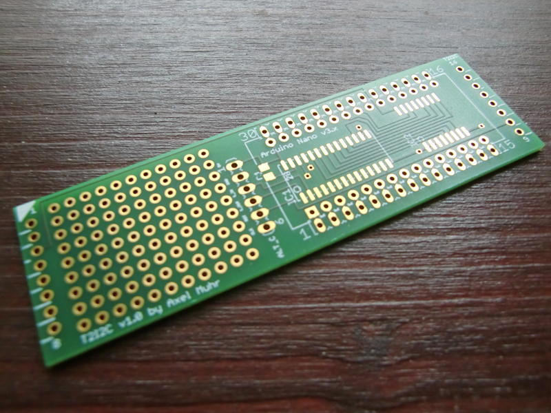
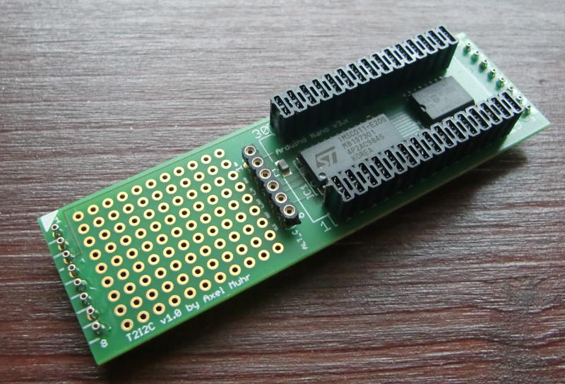
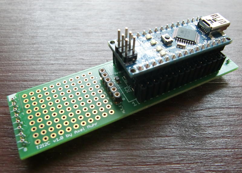
Like you’ve seen in the video, there’s no real circuit board existing yet there wasn’t a real circuit board around back then. But I’ve created a board layout for a TRAM-1 containing an SMD C011 and 8574 which provides the space needed for a socket to plug in anArduino Nano (the small version of an Arduino Duemilanove) – Version 3.x to be precise. You have to use a V3.0 or higher if you want to use my ‘firmware’ out of the box! This is because the analogue pins (A0-A7) have been rotated in V3.x and up – if you plan to use an earlier version of the Nano, you have to adjust the i2c-pin definition in the firmware source.
Anyhow – Using an Arduino Nano is much more flexible -and cost saving- than putting everything incl. the ATMega on the board itself.
The socket is laid out to be “double-row”, so you can still plug wires right next the Arduinos pins – well, actually this is mandatory at least for connecting to the LED panel.

Currently (v1.0) these pins are used/defined by the firmware on Arduino:

  • Portd: 7, 6, 5 and 4 for connecting the LED panel
  • Analogue input pins 4 & 5 (SDA/SCL) for the I2C bus
  • Portd: Pin 2 connects to QVAL, Pin 3 to QACK on the C011

board

I tried to layout the board in such way that it could also be used as stand-alone, i.e. without being seated into a TRAM slot. Then you would have to provide the Links, 5V, GND, a 5MHz clock and Reset yourself via the alternative connector in the middle of the board, called “ALT_C” . There is still room left which I’ve used for a little breadboard section.

This design is to be considered v1.0 – still things to improve, especially a way to choose the link to be used if the board is actually plugged into a TRAM socket. v1.0 routes LinkIn/Out to the ALT_C socket which needs to be air-wired to the TRAM-pins… not nice but does its job.

If interested, you can download the Eagle CAD files here.

After nearly a year I was able to get a hand full of boards created and populated one using my brand new reflow oven (Reworked pizza oven) and voilá, here’s the T2i2c in flesh, naked:

T2i2c_naked

…a bit more dressed (all parts place)…

T2i2c_dressed

…and finally fully dressed (Nano plugged in):

T2i2c_fullyDressed

So the final question was: Will it actually work? Yes it did! I plugged it into slot 2 of my beloved BOZO, connected the LED panel and adjusted my Helios test-sources a bit, and tadaa:

T2i2c

The cool side-effect of this project is, that you can keep the USB cable connected to your host, while the T2i2c is actually running in a system, giving a perfect  OS-link-sniffer for what’s going on in a Transputer setup.

Also, I reworked my Helios tools for checking the T2I2C functionality. Everthing is now in one single tool, i.e. test-pattern, clearing the panel or manually sending a command. Here’s the source as well as the executableread the source header before using! You can crash your Helios system – you’ve been warned!

Outlook

I won’t say the sky is the limit, but if the T2I2C-TRAM will be full-duplex in the next release (ie. C011 in Mode-2) driving an LED panel would be just one of many other uses this TRAM could fulfill.
Think of all the million things people did with their ATMega/Arduinos: LCD-Displays, SD-Card Interface, Ethernet and then some more. Ok, the speed of I2C will limit that somewhat (I already have made prerequisites in my ‘firmware’ to put I2C into 400kHz/kbps “fast mode”) but still a nice interface for connecting today-tech to your yester-tech.

The T2i2c

Boy, my acronyms are really getting Star Wars’ish now… After the T2C64 and the T2A2, T2I2C sounds like a new protocol-robot but stands for “Transputer to I2C (Bus)”.
The I2C bus is a comparably slow serial bus – even to the Transputers 1990 standards – but in contrast to the Transputer OS-link interface I2C is still alive and kicking… even more since those simple-to-tinker-with controllers like ATMEGA or PIC made there way beneath your soldering gun.

As you might have guessed by now, the I2C bus wasn’t my primary intention to do this interface.
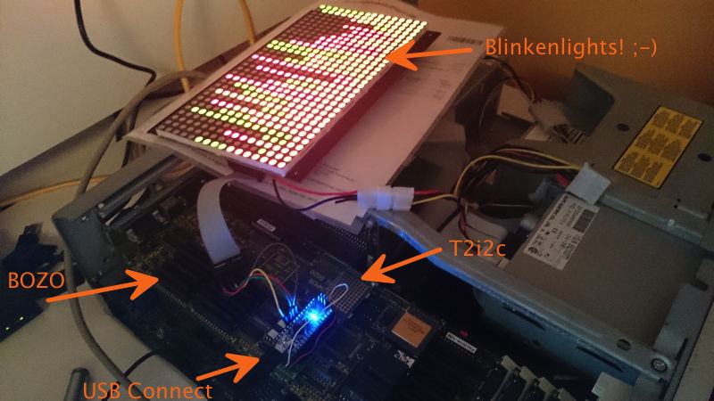
Since I started fooling around with Transputers I was thinking of an LED “CPU load display” like the one the lovely BeBox had… just bigger, a real manly Blinkenlights 😀 It should be at least capable of showing the load of up to 32 Transputers…
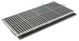
So I stumbled across a very nice bi-color 32×16 LED panel (Sure Electronics DP14211 – it seems in 2022 that company was either sold or folded), which is quite easily controllable through one small ATMEGA controller.

LEDPanel

By incident, a friend of mine gave me an surplus Arduino as a present and the decision was made. I’ve build & programmed ATMEL devices before, but Arduino plus breadboard can’t be beaten if you need to get something done quick.

Blinkenlights

It’s quite straightforward to connect the panel (can one say “display”? Nahh.) to the Arduino. To make things even more ‘bus-y’ the ATMEGA talks over just 4 wires to the panel over SPI bus – yet another serial bus, but luckily we don’t have to care about that fact as there’s a library handling this.
So after some days of coding, the “panel firmware” was done. The Arduino is happily talking to the panel over the SPI bus and listening on his I2C bus (another 4 wires) for commands and sends the calculated output to the panel.

Commands? Well, I was thinking about how to handle the data in an efficient manner. The most simple way would have been to have the Transputer sending the complete 32×16 ‘bitmap’. For a bi-color panel (2 bits per pixel) that would have been 1024bits/128bytes each time/interval.
To be more flexible I came up with a 3-byte command structure – for details see the next post.

Old guy speaking new language

So how to connect a Transputer to an IC2 ‘device’? We need two things for that:

  1. The good ol’ C012/11 Link Adapter – turning Transputer links into an 8-bit parallel bus
  2. An 8bit bus-to-I2C converter

We saw the C012/11 in some of my projects already, so piece of cake here. The 2nd converter needed some research and was easily found: A Philips/NXP PCF8574(A). So without control-lines the setup is quite simple:

Transputer → C012 → PCF8574 → Arduino → LED panel

After some hassle with handshaking (see next post “nitty gritty details”) I was able to send bytes to the display using MS-DOS’debug.exe to write bytes to the standard Transputer link IO ports (0x150++, you should know that by now ;-)) using a nice tool called ‘iskip.btl‘ from the INMOS ANSI-C Toolset (also available in my Transputer Toolkit). It simply shortcuts one Transputer link to another, e.g. Link 0 to Link 2. This relieves you from removing your Transputer and put jumper-wires into its socket… very nice and clean solution.

Doing it the right way

Well, while talking to devices through debug is definitely geeky, it’s not what I wanted as a result.
Having more than one Transputer running, watching its CPU and probably RAM load leads to the inevitable target of Helios. At least that’s the No.1 reason I created this interface… but with the command structure of the ‘firmware’ you’re obviously not bound to that OS, e.g. OCCAM programs could control the panel, too.

So the biggest development part was creating a clean way of taking to the panel while running Helios. For debugging and testing I wrote a simple command-line tool which opens a link on the Transputer you have the shell running on, then it sends what ever byte you added as parameter. Fine.
Next was version 2 of that tool, sending 32 fictional CPU-load values (0-100%), version 3 did the same adding RAM-load values.
Then it was time to do it the right way – so I dived into the sources of ‘network‘. network is the Helios tool for examining the Transputer (not IP!) network(s), so it shows the actual load in nice bar charts etc. – pretty much like top does on todays Unices.
While the sources of Helios are available, they seemed to be accumulated from different sources, dumped into an ISO image without caring for symbolic links etc. – in a sentence: They’re a mess.
After some days of try’n’error I was able to compile the sources of network. This made network2 (working name) possible which includes the new parameter ‘led’ followed by the number of the Transputer link to be used, eg. ‘network2 led 2‘ results in displaying the current CPU/RAM load of all Transputers in the network on the panels.
CPU-load is displayed by red LEDs, RAM-load uses green LEDs, overlapping is shown orange. As long as there are up to 32 Transputers each line represents one Transputer (using 16 LEDs). If there are >32 and <65 each line will be split into 2 columns (8 LEDs for each Transputer). This goes on for >64 and <97 (3 columns) and finally 4 columns for up to 128 Transputers – this isn’t very ‘readable’ anymore given there are only 4 LEDs left for one Transputer, but hey! It’s Blinkenlights, who cares!?

So without much further ado, here’s the prototype-beast in action:

For more details, thoughts, outlook and code see the next post.

3rd party TRAMs

Well, INMOS wasn’t the only company manufacturing TRAMs. This is a -more or less random- collection of TRAMs I was able to find in the WWW.

Because some TRAMs are of unknown origin, I’ll sort them by size…

Size-1 TRAMs

This is my 2nd smallest TRAM by RAM size. 128KB SRAM. The silk-print says “TRAM-1-B” on the front and “TRAM-1-L” on the back. I guess they’re made in Germany as it’s usual to mark the front with B (“Bauteilseite”, component-side) and L (“Lötseite”, solder-side).

TRAM1_32k

This seems to be a very early design, featureing a 16-bit T212 and some original INMOS SRAMs

Unknown_T212A_Module

This is my “standard 1MB” TRAM. It’s labeled “ARADEX T805S“. It seems that the German ARADEX AG, originally manufacturer of cardbox packaging machines built their own TRAMs for their systems. It’s pretty highly integrated. Some but not all of them feature an ALTERA EMP5016 PLD which hold extra logic for the additionally fitted subsystem pins..

ARADEX_T805S_1M_1

Transtech was a quite big manufacturer of all-things-Transputer. They had a big range of TRAMs in their catalogue. Pictured below are the TTM-1 (32KB SRAM), TTM-3 (1MB DRAM) and its successor TTM-7(1MB DRAM).

Transtech_TTM1

Transtech_TTM3

Transtech_TTM7

Here’s another image of which I think it’s an TTM7:

UnknownT1_1MB

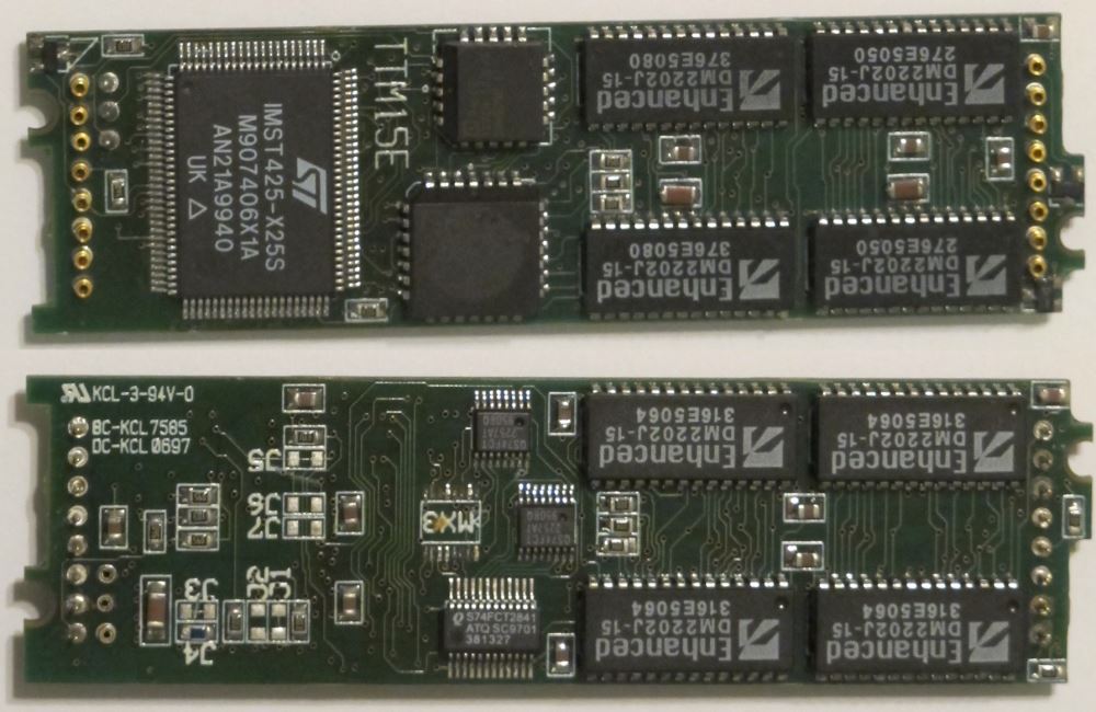
The final TRAMs of Transtech were the TTM15(e) and TTM19(f), both using the SMD package of the T800 as well as the rest of the ICs.

The TTM15E uses some interesting “Enhanced DRAM” from Enhanced Memory Systems Inc.. These include 2K SRAM in each 4Mbit DRAM chip, which increases the access speed to 12ns.
Very neat, very hard to get-by today. Restoration impossible. Mind all the jumpers on the backside – obviously a lot is configurable here.

TTM15E

The TTM19F uses what looks like modern (S)DRAM – need to evaluate that more…

TTM19F

This is a special one: Two Transputers but no RAM. It’s labeled Alcor 2T. Very nice if you need lot’s of CPU-power and can live with the 4K RAM inside the Transputer.

Alcor_2T_no_memory

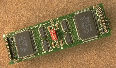
Sundance was another manufacturer concentrating on the Transputer business. They made lots of TRAMs, this SMT213 is comparable to the Alcor 2T but features two T805 Transputers in SMD as well as 1 or 4MB DRAM per Transputer (on the back) and was built in 1993 which is near the end of the Transputer era. With 4MB I’d consider this to be the “Rolls-Royce of the TRAMs”. Yummy!

Sundance SMT213

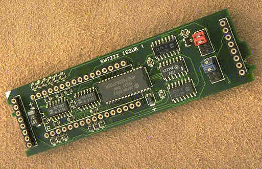
The SMT222 is an EPROM boot TRAM. You can see the socket for a 64-512KB EEPROM, inside the socket is a C011 to provide the DS-Links to the Transputer network.

Sundance SMT222

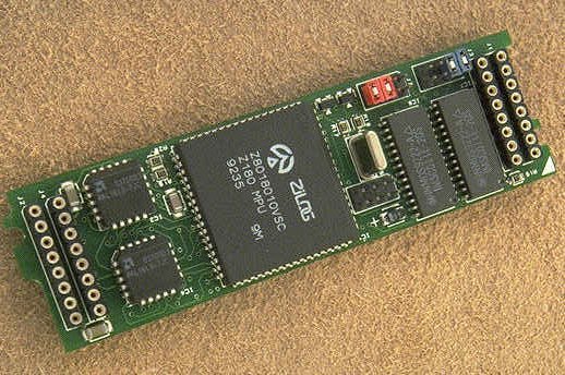
This is the SMT220, Consisting of a Z80 compatible micro controller (Z80180), a 32KByte SRAM data buffer, 512bytes of firmware and two C011 Link adapters, this TRAM is what I call an “RS232/485 interface overkill” – but I guess some industrial use required that.

Sundance_SMT220


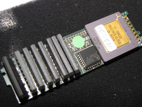
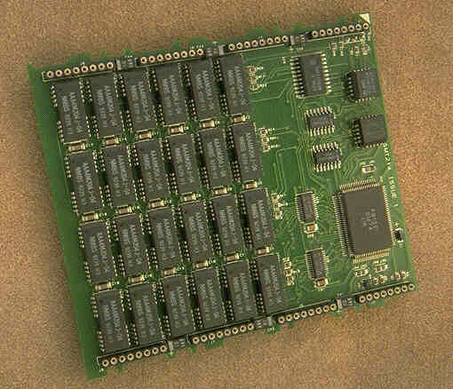
Another TRAM, using seldom used AAA4M204 SOJ DRAMs (4x1Mbit). The label says “Douglas Engineering TTM 15A/7A” (Not sure about the last number given the blurred picture I found).
This one is interesting  in so far, that it is more or less a standard SIMM-on-a-TRAM. This would make a worthwhile retro-project to recycle all those 30-pin SIMMs sleeping in our drawers 😉

DouglasEng_TTM15a_front

DouglasEng_TTM15a_back

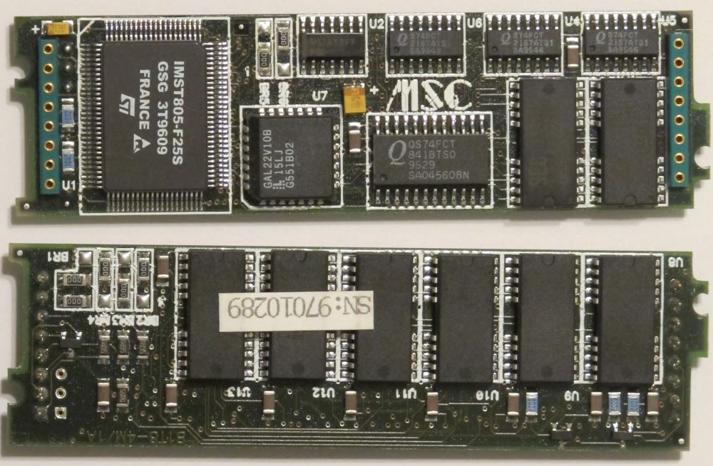
MSC (“Microcomputers Systems Components GmbH”) another pretty much unknown Transputer device manufacturer from Germany also made a SIMM-style TRAM and called it the B1T8-4M/A1.
As with the TTM15E, some settings can be configured by jumpers on the backside.

MSC-B1T8-4M_1A

Size-2 TRAMs

Next up, the STM228, a SCSI TRAM… something you want to get the most performance out of Helios or file-through-output in general.

Sundance SMT228 SCSI TRAM

The SMT229 would be the other TRAM you want for a professional system. This is the most modern ethernet controller available.

Sundance SMT229 Ethernet TRAM

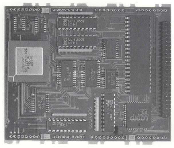
The Transtech TTM-6 is a comparably boring 2MB computing TRAM. It’s an older design, like the IMS B404.

Transtech TTM6

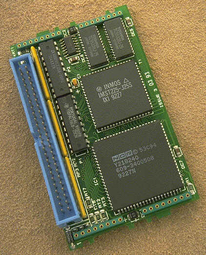
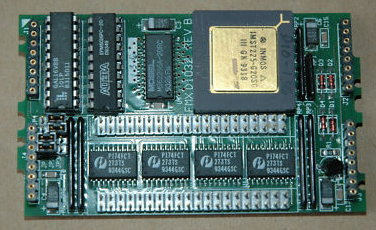
This seems to be some sort of I/O TRAM… lots of 74FCT buffers and a T225. It’s called FMX D1032.

FMXD1032

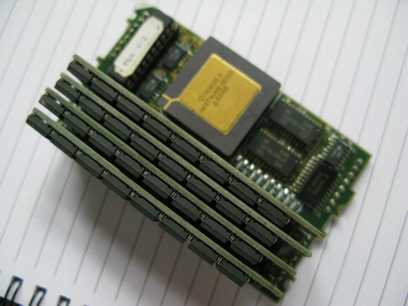
This is an interesting one: A TRAM of unknown origin using SIPPs – as memory(-expansion)!

Very cool, as you could expand its RAM up to 64MB given all addresslines are used. Downside is that this TRAM is building pretty high…

TRAM_mit_SIMM_F

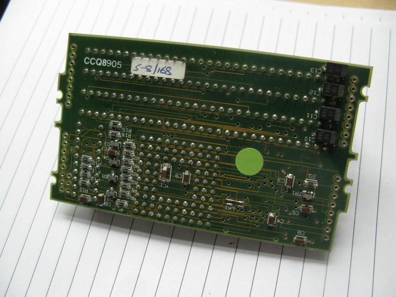
and the back:

TRAM_mit_SIMM_B

Size-4 TRAMs

We’re now coming to the “Big Guns”. Starting with TTM11, another SCSI interface. It’s older than the nice SMT229, so it only has a 16-bit T222 and some old SCSI controller (my guess it’s a WD93xx chip).

Transtech TTM11

This is the Sundance SMT214, a “large memory TRAM”. It was available with 16, 24, 32 or 64MB DRAM including a T805 at 25MHz. This should be sufficient for every Transputer application… as long as nobody ports Windoze to Transputers 😉

Sundance SMT214

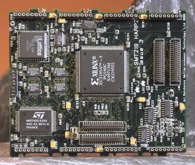
The SMT219 was the commercialized version of the HARP1 project, called HARP2 then. It’s a T425 Transputer connected to an FPGA which could be programmed for any task you needed to get done… a C64 emulator for example 😉

Sundance SMT219

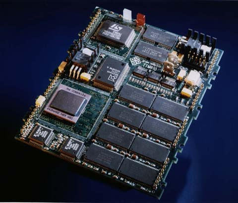
This is where it starts getting funny. Because Inmos was struggling with the next Transputer generation, other CPU manufacturers presented new quite fast  competitors, like the PowerPC from Motorola. This Transtech TTM610 featured not only a T805/25 but also a 200MHz PPC603 or 604 with 16 or 32MB of RAM.

TTM610 PowerPC TRAM

Parsytec thought the same and presented the ‘PowerTRAM’, an 80MHz PPC601 on a TRAM. Well, and there’s a T425/25, too.
If you like to know more, the Parsytec PPC systems have their own post over here.

Size-6 TRAMs

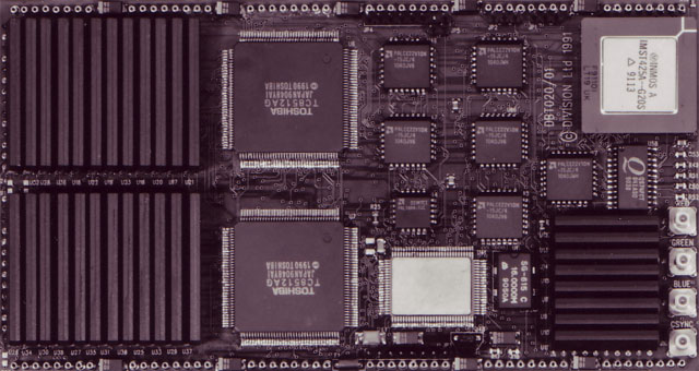
This is an graphics TRAM from “Division Ltd.” probably called DBT020/01. It features a T425 with its own 1 or 4MB RAM and 2 Toshiba TC8512 “Gouraud shading processors”, some VRAM and most likely an Inmos IMS Gxxx graphics controller.

DBT020 - unknown graphic TRAM

Size-8 TRAMs

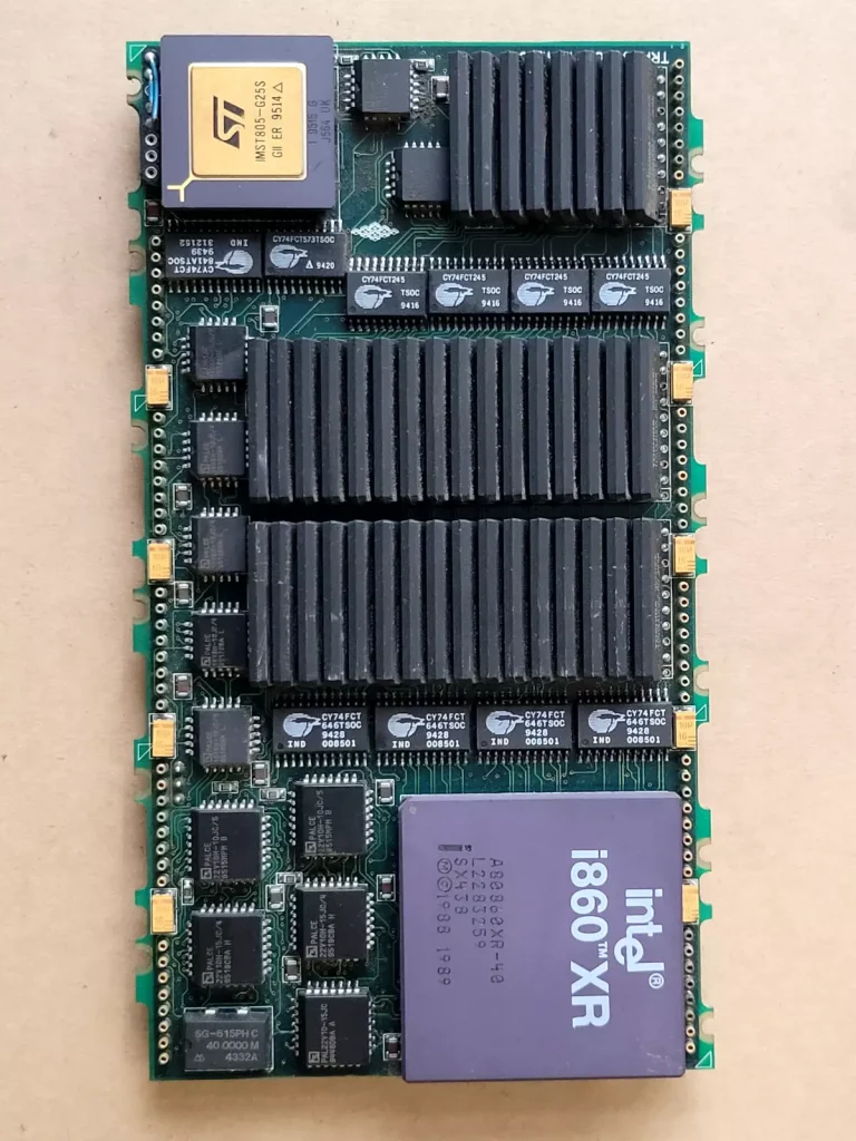
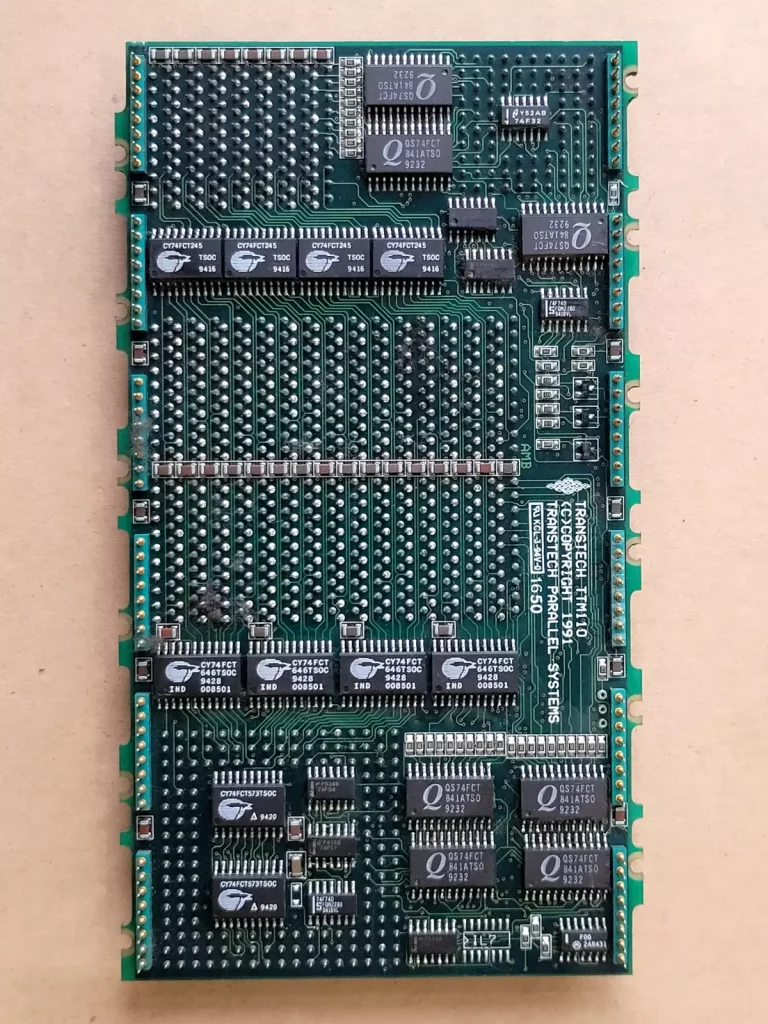
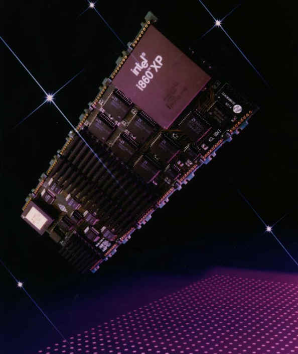
This huge beast is a TTM220 with 16 or 32 MByte DRAM coupled to both an Intel i860XP  processor, and a T805 transputer. There was a bit smaller (size-6) version called TTM110, too.
All in all it provided the same features like the DSM860 cards (well, despite the 32bit Transputer).

TTM110 TTM220 i860 TRAM

(To be continued)

HTRAMs

As the T9000 had so many new features and architectural differences the “classic” TRAM wasn’t enough to support all that. So INMOS went to enhance the TRAM-model…

And they meant it! Instead of DIL 16 Pins of a “classic” TRAM, HTRAMs could use up to 160(!) pins to communicate to the outside world. Besides the classic 5V, also 3.3V was supplied on one pin as a tribute to the technical progress. Due to the introduction of the DS-Links (vs. OS-Links within the T4xx familiy), each of the four links of the T9000 now required 4 pins per link, resulting in 16 pins for the links alone. Plus many other special links for Events, ConfigUp/Down etc. a minimum of 60 pins were used.
Also each HTRAM now featured a PROM so it could be identified by software.

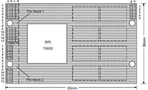
This is the pinout of an HTRAM extracted from the most recent source (SGS-Thomson B92x HTRAM datasheet, Nov. ’94)

HTRAM

Pin Row a Row b Row c Row d Row g Row h
1
2
3
4
5
ClkIn
L0SIn
L0DIn
L0DOut
L0SOut
N/C
GND
N/C
V3V3
N/C
TDI
V5V0
CupSIn
GND
CUpDIn
notTRST
L2SOut
L2DOut
L2DIn
L2SIn
EventIn0
EventIn1
EventIn2
EventIn3
EventOut0
EventOut1
EventOut2
EventOut3
9
10
11
12
13
L1SIn
L1DIn
L1DOut
L1SOut
Reset
N/C
V5V0
N/C
GND
TMS
CUpDOut
GND
CUpSOut
V3V3
TCK
L3SOut
L3DOut
L3DIn
L3SIn
V5V0
1
2
3
4
5
N/C
N/C
N/C
N/C
N/C
TDO
GND
CDnSOut
V3V3
CDnDOut
9
10
11
12
13
N/C
N/C
N/C
N/C
N/C
CDnDIn
V5V0
CDnSIn
GND
N/C

While many (i.e. 100) pins left unspecified in this pinout-map (e.g. Block 2 rows c & d, Block 3 rows e & f and the complete Block 4), they’re all used on the HTRAMs I own.
My guess is that those were used for the memory-bus, at least in the case of my Quintek board.

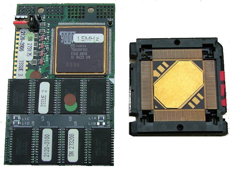
Here’s an original INMOS HTRAM, with a 15MHz T9000 engineering sample mounted, plus a T9000 (backside) next to it:

HTRAMandT9k

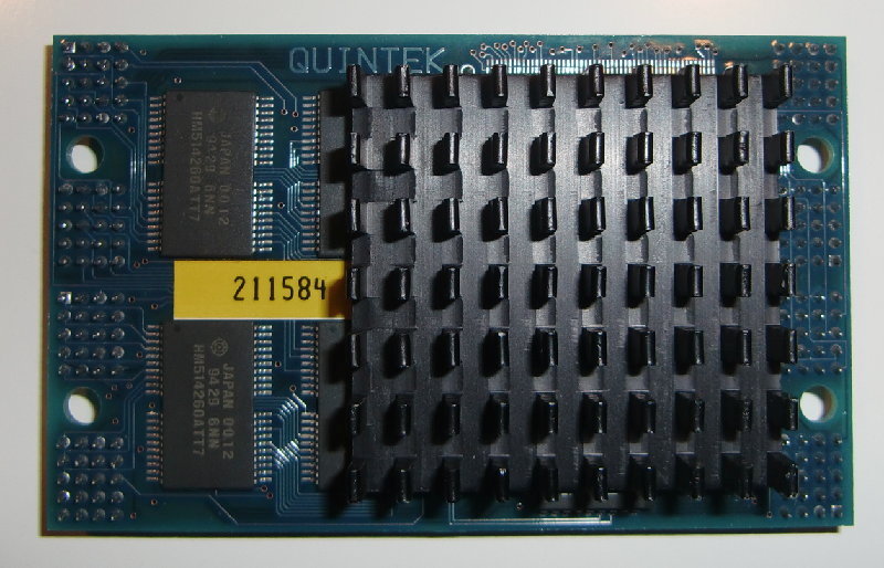
For a quickstart here are the 3 HTRAMs from Quintek which I own:

QT9A

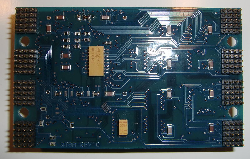
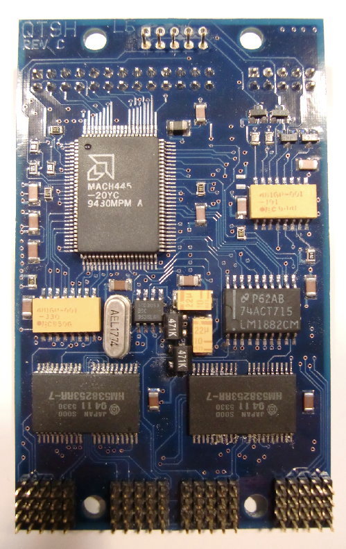
The QT9A (Rev.C in this case) is a processor HTRAM of (yet) unknown clock-speed and memory-size – I think it’s 4MB. Because the T9000 ran really hot in the prototype stage (which he never left), all of them required a compariby big heat-sink. I do not dare to remove it, given the (collector) value.

QT9A_front

…and the backside for completeness 😉

QT9A_back

QT9H

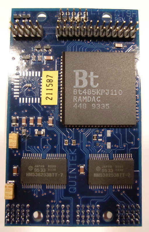
This is a display HTRAM featureing a Bt485 RAMDAC, 2MB VRAM but no video-output part. The video signal is delivered to a pin-row which is going connected to a VGA-featurebus on a graphics card. It’s a Rev.C part, like the QT9A.

This and the following HTRAM were fitted into Slots 5 and 5 on the HTRAM-board which are quite special slots: They don’t offer the pin-blocks 1 & 2, i.e. no DS-Links etc.! That said they do feature fully populated pin-blocks 3 & 4 which underlines my assumption that those pins are meant for direct memory-mapping.
In the case of a Video & Encoding HTRAM this makes totally sense because it gives the Transputer even faster access to the Video-RAM than pumping all the data over the Links.
Which leaves yet-another-riddle-to-be-solved: Where are those HTRAM mapped into the T9000s memory?

QT9H_front

…quite a lot is happening on the back-side, too:

QT9H_back

QT9C

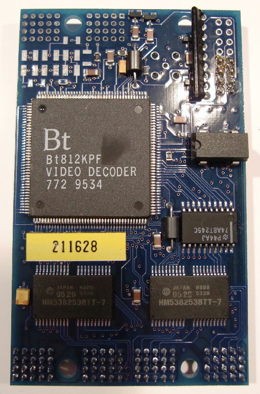
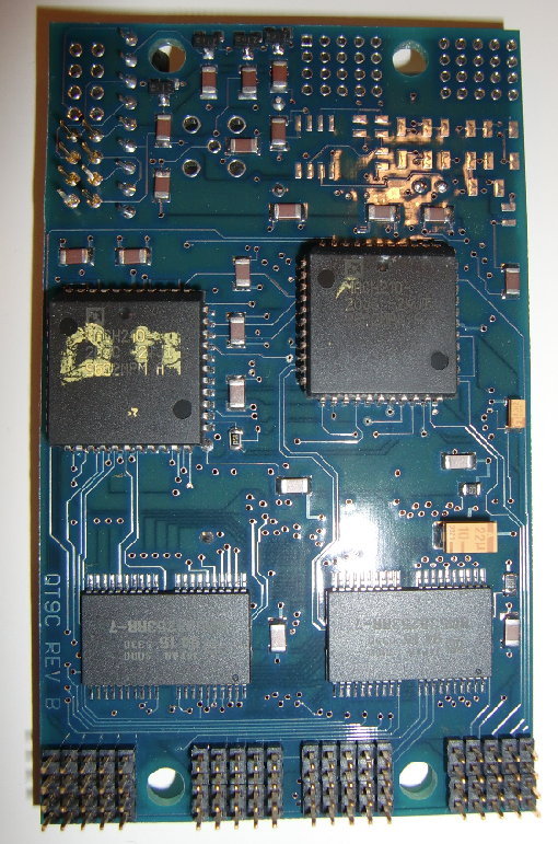
A video digitizing HTRAM using the BrookTree/Conexant Bt812 chip and having 2MB VRAM, too… this time “Rev.B”.

QT9C_front

and the back side…

QT9C_back

To be continued…

The Inmos B020

Well, normally I wouldn’t list Inmos’ expansion cards here, as they’re normally just TRAM carrier boards and very well documented at the usual places… but for this card, it’s different.

Not only that there isn’t any documentation of the IMSB020 (just a brochure over at Rams page) but this specific card is an updated version of that described in the brochure… I’d call it Rev.2.
It has a T805 instead of a T4xx and probably some more additions…

Ok, first of all: What is the Inmos B020 anyway? It’s being sold as a “X11 server on a card”… I’m intentionally writing ‘being sold’ because that just one way of usage.
More generally spoken, it’s an ISA card with a Transputer (with 4-12MB RAM) and a graphics controller on it, an Inmos G332 to be precise. That Transputer controls the G322 and can therefore create graphics onto a VGA screen connected to the board.

As an avid reader of GeekDot, this should sound familiar to you because it was the typical 90’s approach of High-End Graphics… see the MiroTiger or the SPEA i860 boards.

With the right software being booted into the Transputer, it may act as a X11 (R4) Server… but it could also used as a native Transputer system, e.g. running Helios or some OCCAM code and still create graphics with the G332 controller. As a nice add-on, the card features two size-2 TRAM slots, so more transputers or devices could be added into the equation.
Ah -and as a side note- most people called the B020 “the BOZO“… not very kind but it gets a credit for its pre-l33tc0de usage.

This is how my ‘rev.2’ looks in it’s full glory:

B020full_small

As usual, we go into more detail looking at each half of the card.In this full-view, you can identify the two TRAM-slots by the yellow markings at the lower edge of the card saying “SLOT 0” and “SLOT 1”.

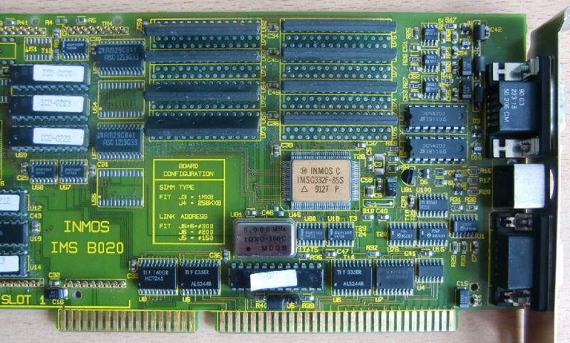
So let’s start with the right half of the B020:
B020right

At the right-most edge, there’s the VGA-in and VGA-out connector, so that you can loop-through the video signal from your regular graphics-cards (a fancy ET4000 for example ;-)).

Between the two VGA connectors is an 8-pin Mini-DIN connector, which has this pinout:

1 Error/ (in)
2 Analyse (out)
3 Tram2 Link 2 out
4 Ground
5 Tram2 Link 2 in
6 Onboard T800 link1 out
7 Reset (out)
8 Onboard T800 link 1 in

The upper 2/3, starting with the golden IC (IMSG322F-85F) is all graphics part. Which consists of the G322 controller, 1MB VRAMabove him and some latches and 3 PALs on the left of it.
Below the G322, next to the slot-connector is the ISA interface. That’s handled by a PAL (with the sticker peeling off) and 4 buffers/transceivers and a bit more “chicken food” around them.
Of course there’s also the inevitable 5MHz oscillator which is needed in every Transputer household.

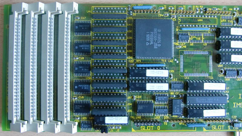
Let’s move to the left half of the card:
B020left

This is ‘where the music plays’. At the lower edge of the right side you can spot the C012 guarded by two PALs (with white labels) who handles the ‘Bus data-to-Transputer’ translation. The two PALs are most likely the subsystem (i.e. handling Reset, Error, the 012’s RS0/1 registers etc.).
Then there is the King of the Hill, the Transputer himself – a T805-25 in a quite rare PLCC packaging. To his left are 4MB of RAM in ZIP-packaging, most likely configured and controlled by the two PALs below him.
Finally, there are 4 SIMM slots to expand the Transputer memory further to a whopping 8MB! As you can easily see, there are unpopulated solder-pads between the ZIP-RAM ICs (as well as the VRAMs). My assumption is that you could order this card with 8MB soldered, which lead to a max. RAM of 12MB, like mentioned in the brochure on Rams page. But I fear the PALs of the RAM-subsystem need to be programmed accordingly to support the larger amount of RAM (added later: And boy was I right!).

So much for the theory of the B020… and it might stay so for some time, because my B020 is was broken 🙁

But I’m working on it and one fine day you will see an X11 server in an XT-PC at blazing speed 🙂
B020LA

Resurrection

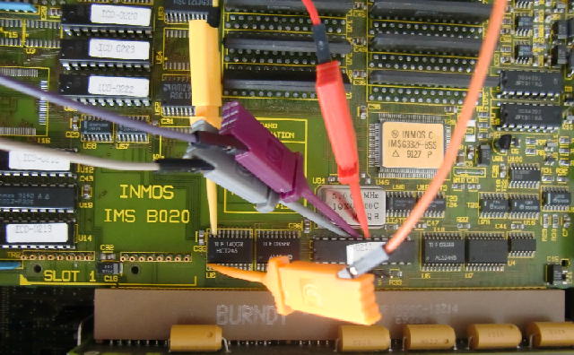
[Nearly 4 weeks later…] As promised, I worked hard on getting the BOZO back to life. It started with weeks of tracing connections of the complete bus-interface, ie. ISA-Bus to the buffers/transceivers, the PAL next to the ISA-bus, the C012 link-adapter etc.etc…
Then, knowing the signals now, came days of staring at the logic analyser, many many mails with Mike Brüstle and lots of hacking with DOSes debug.exe.
Finally it became clear that the PAL 0211 was somehow “confused” and therefore not controlling the bus as it should do. Because there’s no documentation neither of the B020 nor of its PAL equations (like there is for e.g. the B008) I had to go the long and bitter route of reverse-engineering.

So first thing is to remove the faulty part which proved to by a bit tricky – which is a short story of its own available in the DIY-section of this page.
So in went a proper socket and a copy of the original PAL (now a “modern” GAL). The copy proved to be a 100% one… which means not working as it should. But somewhat different than the tries I did before…it was erratic. For example only on I/O port 0x200 I was able to get something useful out of the signals (eg. a well timed /OE for the ‘244 buffers) while jumpering the IO range to 0x150 or 0x300 gave total silence. So I went one step closer to the bus, listening to what the PAL gets on its A4-A11 lines.
There you go! A4-A6 were constantly high and A7 glitching while A8-A11 was happily bouncing. According to my tracing A4-A7 were handled by a different ‘244 than those working. So Sauron turned his eye on the little SMD octal buffers… out went the solder iron and all pins of all buffers were re-soldered.

Lo and behold, the next ispy run on 0x200 worked! Heureka!

Next up: Why is it working on port 0x200 only? Learning from the ‘244 issue I checked all solder-pads concerning the jumper for port 0x150 (that’s J5). Everyhing looked nice and re-soldering didn’t change a bit. So it was the PAL who was suspicious… again.
Luckily INMOS refrained from setting the protection fuse on the PAL, so not only I was able to copy it but also the read its programming. I was thinking about recoding the whole thing and started doing so when I stumbled across a missing “.oe” (Output Enable) for exactly that input-pin connceted to the J5 jumper. So quickly adding

/f14 = gnd
f14.oe = gnd

to the code, compile, burn, plug it into the socket. Tadaa! The B020 now also talks to 0x150… and 0x300 respectively.
[BTW: This happened right at the 30th birthday of DOS. Don’t know if it’s a good or bad sign… at least DOS is my favourite debugging tool 😉 ]

For those who happen to have the same issues with their B020 (erm, that’s probably 1-2 people on this planet by now), here’s my documentation and .jed file for the “PAL 0211B”.

Enhancement

Well, as said in Axels 10 commandments: “Thou should not leave a socket unpopulated!”
And my B020 has a lot of ’em. So I started with the Transputer RAM.
In preparation I checked if the empty solderpads (as you can see in the above pictures) do get all the required signals… well, kind of: I was lazy and just checked /OE with my logic analyser and there was a signal in sync with the one of the already installed RAM. Also all Data- and Addresslines were connected… so it was worth a try!

But I should have known it before: After clearing all 160 pin-holes from the solder, puting self-made zig-zag sockets in place and filling them with the appropriate 1Mx4 RAM chips ispy/mtest still reported just 4MB of RAM :-/

Obviously PAL0214, sitting right below the ZIP RAM was playing an important role here. So the good old routine of “buzzing it through” began. After 2 days I pretty much figured out the purpose of each pin of PAL0214. Yes, it must be the RAM decoder.
So there was no way around removing, reading and replacing it… like with PAL0211.
This time I got myself a desolder-gun – a hell of a facilitation! Again, luckily the PAL wasn’t protected so reading it wasn’t an issue.
As expected, the decoding for the 2nd RAM bank was missing – no idea where the initial measured /OE signals came from.
After the decoding of 1st 4MB ZIP RAM the SIMM RAM followed immediately – so I had to squeeze in the 2nd bank of 4MB ZIP RAM and let the SIMM RAM follow after that. Even my VHDL/PAL Equation skills are quite limited it wasn’t as hard as I expected. Compile, program, put the new GAL16V8 in place, start ispy/mtest, cross fingers….

Using 150 ispy 3.23 | mtest 3.22
# Part rate Link# [  Link0  Link1  Link2  Link3 ] RAM,cycle
0 T805d-25 340k 0 [   HOST    ...    ...    ... ] 4K,1 12284K,4;

Yay! 12MB including the SIMM RAM!! Here’s the view of a “BOZO to the MAX” 😉
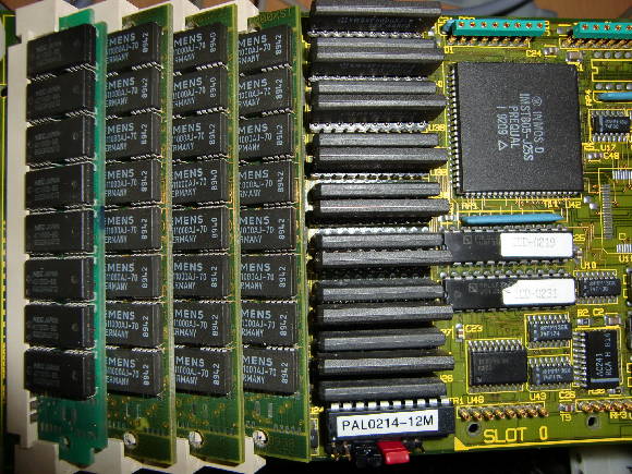
BOZO_full_RAM

Double the VRAM!

The last step in bringing the BOZO “to the max” was adding more VRAM, i.e. 2MB.
So first you have to get two more AM29C841 9-bit latches (or compatible parts, like those 74FCT841 I’ve used) in SO-24 package. That SMD package is still quite easy to solder onto the board. Here’s a before-and-after picture:
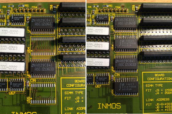
BOZO_VRAM1

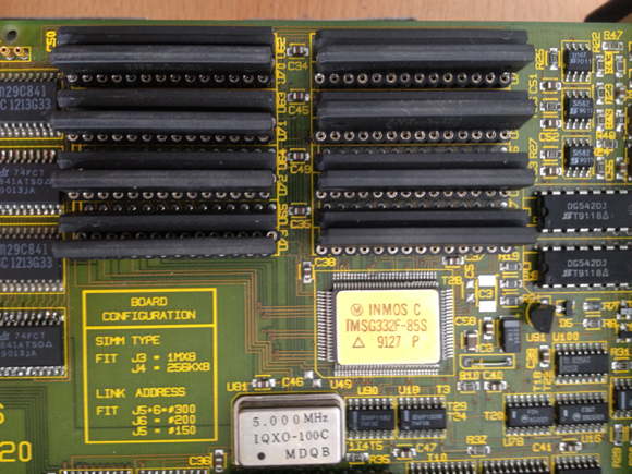
On the right-hand side of the latches you can already spot the empty solder-holes for the VRAM. Like with the DRAM expansion before, I made my own sockets by using two 1×14 pin sockets. This is what the now fully populated VRAM section looks afterwards:
BOZO_VRAM2

The first run using “ixcheck” from the INMOS iX package went without errors and the /OE signals of all the ‘841s are driven correctly according to my logic analyzer. I was a bit scared that INMOS might have again not completely programmed the PALs (left to the latches) to support this memory expansion but it seems I’ve been lucky.

Next up: Find a tool using the 2MB and confirming that the extra VRAM is actually usable.